PanelDue 5i Neither Temperature nor Toor displaying
-
Hello!!
I've connected a PanelDue 5i to my printer using a 4-core cable and a Duet 3MB 6HC Board. Currently, I can perform tasks like homing, fan activation, and stopping the printer. However, I'm experiencing a few issues:
-
The display shows "connecting," but the heaters (I have 3 for my printer) and the tool aren't appearing as expected (see Photo 1).
-
I'm unable to send commands from the console.
At the moment of writing this (It seems like it can detect that I'm complaining.)
--> The display has gone completely black (see Photo 2), and the voltage at the C3 pin reads 1.170V.
I've tried connecting it to my computer through USB, and it worked. I also successfully re-flashed the firmware using BOSSA. However, when connected to the board again, it remains black (not sound if I touch), so I don't think it's a backlight converter. I've verified that the pins are connected as shown in Photo 4 and the pozer supply give me 23.25V.
My PanelDue is running version 3.5.0-rc5-5.0i (see Photo 3), and both my config.g file (attached below) and the PanelDue are set to a Baud rate of 57600 (see Photo 3). However, the IP address isn't appearing (see Photo 3).
Confg.g
;Welcome to your configuration GigabotX_ Western_University
M291 P "Welcome to your experence using the GigabotX_ Western_University" S1 T0; General preferences
M575 P1 S1 B57600 ; enable support for PanelDue
G90 ; send absolute coordinates...
M83 ; ...but relative extruder moves
M550 P"Gigabot X UWO edition" ; set printer name; Network
M552 P192.168.100.8 S1 ; enable network and set IP address
M553 P255.255.255.0 ; set netmask
M554 P192.168.100.254 ; set gateway
M586 P0 S1 ; enable HTTP
M586 P1 S1 ; enable FTP
M586 P2 S0 ; disable Telnet; Drivers
M569 P0.0 S2 ; physical drive 0.0 goes forwards X
M569 P0.1 S1 ; physical drive 0.0 goes forwards YR
M569 P0.2 S0 ; physical drive 0.0 goes Backwards YL
M569 P0.3 S1 ; physical drive 0.3 goes forwards ZR n ZL
M569 P0.4 S1 ; physical drive 0.4 goes forwards Extruder
M569 P0.5 S1 ; physical drive 0.4 goes forwards Crammer
M584 X0.0 Y0.1:0.2 Z0.3 E0.4:0.5 ; set drive mapping
M350 X16 Y16:16 Z16 E16:16 I1 ; configure microstepping with interpolation
M92 X53.335 Y59.26:59.26 Z2015.75 E 26.00:34.00 ; set steps per mm E extruder:crammer
M201 X500.00 Y500.00 Z20.00 E900.00 ; TEST set accelerations (mm/s^2)
M203 X10740.00 Y6810.00 Z480.00 E3600.00 ; TEST set maximum speeds (mm/min)
M566 X900.00 Y900.00 Z60.00 E500.00 ; TEST set maximum instantaneous speed changes (mm/min)
M204 P5100 T20000 ; set printing and travel accelerations (mm/s^2)
M906 X2800 Y2000:2000 Z2000 E850:2000 I30 ; set motor currents (mA) and motor idle factor in per cent
M572 D1 S0.03 ; Set extruder pressure advance
M84 S30 ; Set idle timeout; Axis Limits
M208 X0 Y0 Z0 S1 ; set axis minima
M208 X600 Y760 Z890 S0 ; set axis maximaEndstops
M574 X1 S1 P"!io1.in" ; configure switch-type (e.g. microswitch) endstop for low end on X via pin io1.in
M574 Y1 S1 P"!io3.in+!io2.in" ; configure switch-type (e.g. microswitch) endstop for High end on YR and YL via pin io3.in + io2.in
M574 Z1 S1 P"!io4.in" ; configure switch-type (e.g. microswitch) endstop for High end on ZR and ZL via pin io4.in;Z-probe
;M950 S0 C"!io7.out" ; configure BLtouch Z in pin io7.in
;M558 P9 C"!io7.in" H10 F120 T6000 ; disable Z probe but set dive height, probe speed and travel speed
M558 P5 C"!io5.in" H10 F120 T6000 ; configure switch-type (e.g. microswitch) endstop for High end on ZR and ZL via pin io5.in
G31 X20 Y-10 Z1.6 P100
M557 X50:600 Y50:754.5 S80 ; define mesh gridHeaters
M308 S0 P"spi.cs0" Y"thermocouple-max31856" A"Bed" T "k" F 60 ; configure sensor 0 as thermocouple via CS pin spi.cs0
M950 H0 C"out0" T0 ; create bed heater output on out0 and map it to sensor 0
M307 H0 B0 R0.367 C336.3 D2.47 S1.00 V23.2 ; disable bang-bang mode for the bed heater and set PWM limit
M140 H0 ; map heated bed to heater 0
M140 S60 R50 ; heated bed "S" active temp "R" standby temp
M140 S-273.1 ; switch off bed heater
M143 H0 S110 ; Heated Bed Max temp
M308 S1 P"spi.cs1" Y"thermocouple-max31856" A"Bottom" ;T "k" F 60 ; configure sensor 1 as thermocouple via CS pin spi.cs1
M950 H1 C"out1" T1 ; create nozzle heater output on out0 and map it to sensor 1
;M301 P32.00 I4.00 D74.00
M307 H1 B0 R0.10 C970 D20 S1.00 V23.9 ; disable bang-bang mode for heater and set PWM limit
;M307 H1 B0 R0.16 C3600 D60 S1.00 V23.9
M143 H1 S280 ; set temperature limit for heater 1 to 300C
M308 S2 P"spi.cs2" Y"thermocouple-max31856" A"Middle" T "k" F 60 ; configure sensor 2 as thermocouple via CS pin spi.cs2
M950 H2 C"out2" T2 ; create nozzle heater output on out1 and map it to sensor 2
;M301 P32.00 I4.00 D74.00
M307 H2 B0 R0.20 C500 D20 S1.00 V23.9 ; disable bang-bang mode for heater and set PWM limit
M143 H2 S280 ; set temperature limit for heater 1 to 280C
M308 S3 P"spi.cs3" Y"thermocouple-max31856" A"Top" T "k" F 60 ; configure sensor 3 as thermocouple via CS pin spi.cs3
M950 H3 C"out3" T3 ; create nozzle heater output on out2 and map it to sensor 3
;M301 P32.00 I4.00 D74.00
M307 H3 B0 R0.25 C2160 D70 S1.00 V23.9 ; disable bang-bang mode for heater and set PWM limit
M143 H3 S280 ; set temperature limit for heater 3 to 280C; Fans
M950 F0 C"out9" Q30 ;"Refroidissement de couche" create fan 0 on pin out5 and set its frequency
M106 P2 S255 H-1 ; set fan 0 value. Thermostatic control is turned off
M950 F1 C"out8" Q500 ; create fan 1 on pin out3 and set its frequency
M106 P1 S255 H-1 ; set fan 1 value. Thermostatic control is turned off
;M950 F2 C"1.out4" Q20 ; create fan 2 "vibrateur Motor" on pin out4 and set its frequency
;M106 P3 S1 H-1 ; set fan 2 value. Thermostatic control is turned off; Tools
M563 P0 S"Pellet extrudeur" D 0:1 H1:2:3 F0 ; define tool 0
M567 P0 E1:1
G10 P0 X0 Y0 Z0 ; set tool 0 axis offsets
G10 P0 R140,0: 140,0 S140,0:140,0:140 ; set initial tool 0 active and standby temperatures to 0C; Miscellaneous
M501 ; load saved parameters from non-volatile memory
;Automatic power saving
M911 S20 R22 P"M913 X0 Y0 G91 M83 G1 Z3 E-5 F1000" ; set voltage thresholds and actions to run on power loss.PHOTO.1
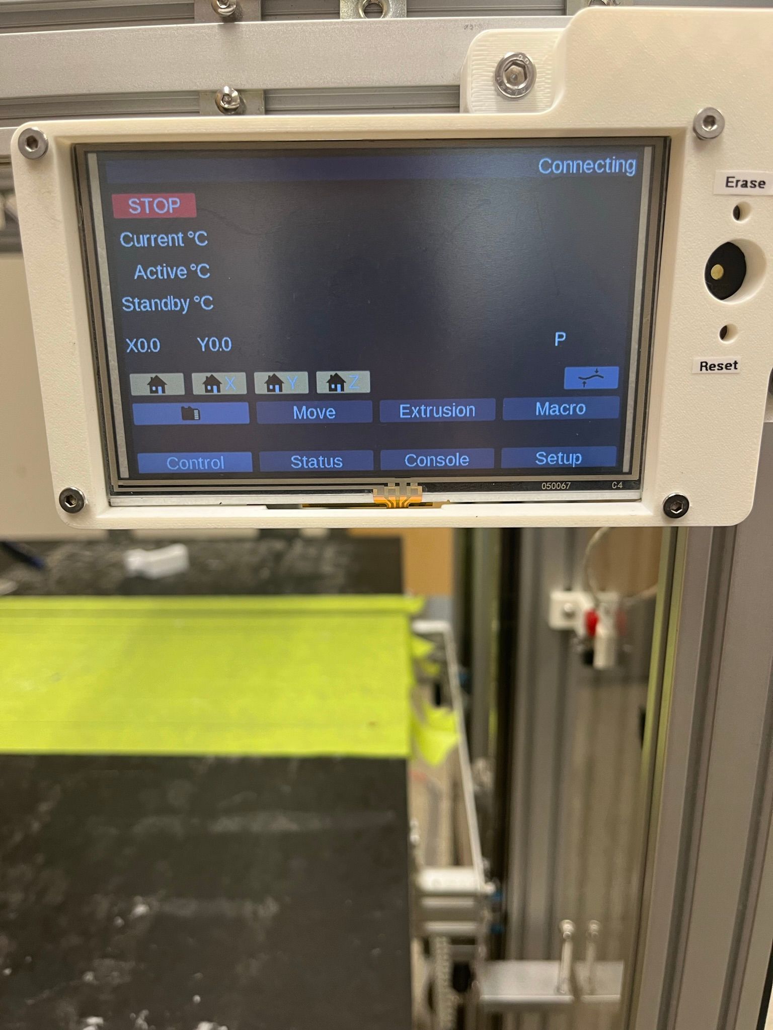
PHOTO.2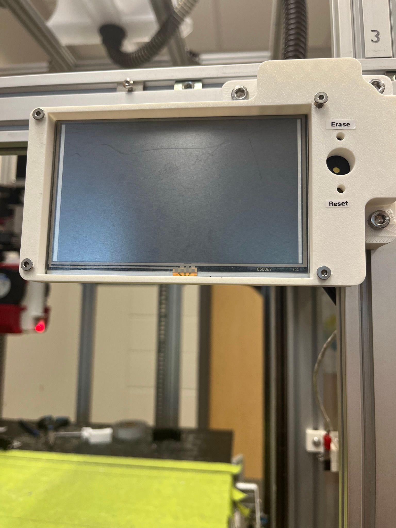
PHOTO3.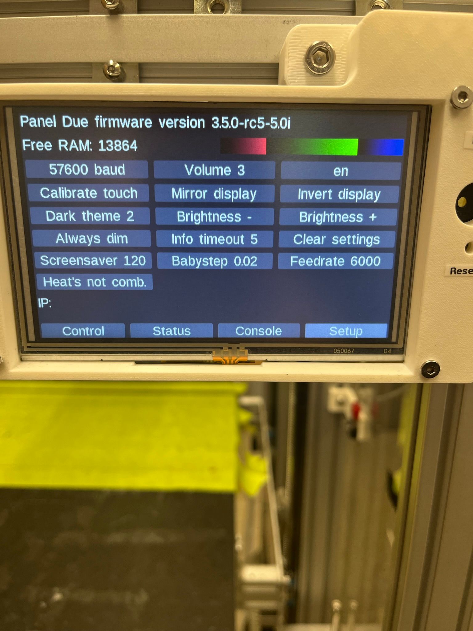
PHOTO4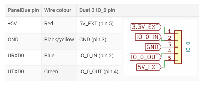
Could you please help me @dc42, @Phaedrux?
By the way, this is the second PanelDue I've tried. Interestingly, I had a similar issue with the previous one; however, the other one make a sound when I touched it and remained black when I connected it to the computer.
Thank you and have a good day.
-
-
@Casugo I'd say check your wiring/crimping. If the PanelDue is blank, and most likely powered off, either 5V or ground wire are not making contract. If you can send commands, but nothing is showing, most likely the wire to IO_O_OUT (usually green to PanelDue Din pin) is not making contact.
Your PHOTO4 image, showing the wiring, is incorrectly labelled; I've updated the table here: https://docs.duet3d.com/en/Duet3D_hardware/Accessories/PanelDue#wiring
Ian
-
What firmware version is the Duet running? SBC mode or standalone?
Also please confirm that you're using IO_0 on the Duet3? I know you show the photo of the wiring diagram, but just want to make sure you're using the right port. -
@droftarts, @Phaedrux, It seems that I encountered an issue with the cable I initially used. I replaced it with the one provided with the panel, modifying one end to connect it to the Duet 3MB. The result is a perfectly functioning setup now.
Thanks a lot
")
-
 undefined droftarts marked this topic as a question
-
undefined droftarts has marked this topic as solved