Help, cannot connect via USB
-
@droftarts Thanks for the reply!
So I have gone through that troubleshooting page. All the status lights on my board indicate that it is working fine. When I plug in the USB I unplug the power supply, should I have the power supply on while I have the USB plugged in? Also the second step of the troubleshooting page "Connect to a PC via USB and look for the port" I thought would apply to me but I can't get my device to show up in the device manager for either of my computers. And for the last step my USB cable is fine and non of the other ports on my computer show the Duet 3, I used this same setup when I initially updated the firmware and it worked as expected. Only after I wired everything up and configured the SD card do I have this issue.
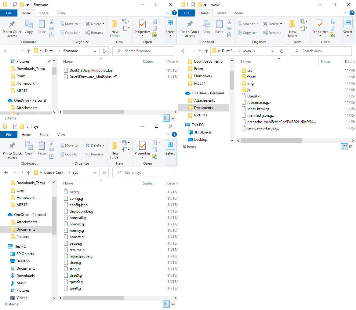
Here is a figure showing the other folders with content in my SD card. the other folders you mentioned are blank per the SD card structure.
-
@Jman3 with the mini 5+ plugged in, rapidly double tap the reset button. does it show up (as a folder) then?
If so, just drag and drop the uf2 firmware file onto the folder/drive that (hopefully) appears -
@jay_s_uk Should it be plugged into the usb and the psu or only via usb? I'm a little worried to reset my board at this point. does that only remove the uf2 and I just have to add it back?
-
@Jman3 the duet 3 mini is pretty hard to break in terms of firmware updates etc. putting it into reset mode won't damage anything and if you don't drag a new firmware file onto it then nothing gets overwritten (but i think in this case that doesn't matter anyway). Its a lot easier than dealing with BOSSA on the duet 2 and duet 3 boards.
You can do it with either just USB power or USB + PSU. Just be aware of ground loops https://docs.duet3d.com/en/User_manual/Overview/USB_ground_loops although i personally have never had an issue (wiring is pretty good in the UK) -
@jay_s_uk Okay thanks, I'll give this a shot today after work.
-
@Jman3 The third step on the page says:
Connect your Duet to a PC using the USB cable. Do not apply VIN power to the Duet at this point.
So no, it's best not to turn on mains power. The logic of the board will be powered by USB.
It sounds like you may be using a cable that only supplies power, not data, ie it's just a charging cable. Is it the same cable you earlier tested the Duet with?
The SD card layout looks correct, though you're not actually looking at the SD card, you're looking at a copy of the SD card contents in your 'Documents' folder. Would be better to see the actual card contents to confirm it is correct.
Ian
Bed-slinger - Mini5+ WiFi/1LC | RRP Fisher v1 - D2 WiFi | Polargraph - D2 WiFi | TronXY X5S - 6HC/Roto | CNC router - 6HC | Tractus3D T1250 - D2 Eth
-
Okay good, I'm glad I followed that step about the PSU. Good call on the cable it looks like I had the wrong cable. I must have switched it out since last time and didn't realized the new cable wasn't transmitting data. I should have thought of that, thank you so much!
This might be a dumb question but how would I access the actual card contents rather than just looking at what's in the folder?
-
@Jman3 said in Help, cannot connect via USB:
This might be a dumb question but how would I access the actual card contents rather than just looking at what's in the folder?
You need to take the SD card out of the Duet, and connect it to your PC somehow. This is usually done with a USB adapter, or laptops often have SD card ports. You can also get a micro SD to SD card adapter. Then the SD card will show up on your PC like any other removable drive.
I assumed you had done this when you said:
I wired up the board and ran through the configuration tool formatted my SD card erasing all the data on it originally.
The screenshots you showed don't show the contents of the SD card, they show what is in the Document folder of your PC; it is highlighted on the left hand side, and the path at the top says 'Duet 3 Conf ... > sys' which is part of the filepath to the files on your computer. Have you copied these files to the SD card? Unless you uploaded them to the SD card when you could access DWC, there's no other way of getting them there.
Ian
Bed-slinger - Mini5+ WiFi/1LC | RRP Fisher v1 - D2 WiFi | Polargraph - D2 WiFi | TronXY X5S - 6HC/Roto | CNC router - 6HC | Tractus3D T1250 - D2 Eth
-
Oh I think I understand, those were the files I put on the SD card originally I just saved a backup on my desktop. The files I showed are the same thing that is on my SD Card, I had copied them over after the configuration. Sorry for the confusion.
-
I did want to ask another question related to this, let me know if this should be its own thread.
After getting my configured SD card and I try to run my first check (Step 3 in https://docs.duet3d.com/en/How_to_guides/Commissioning).
M98 P"config.g"
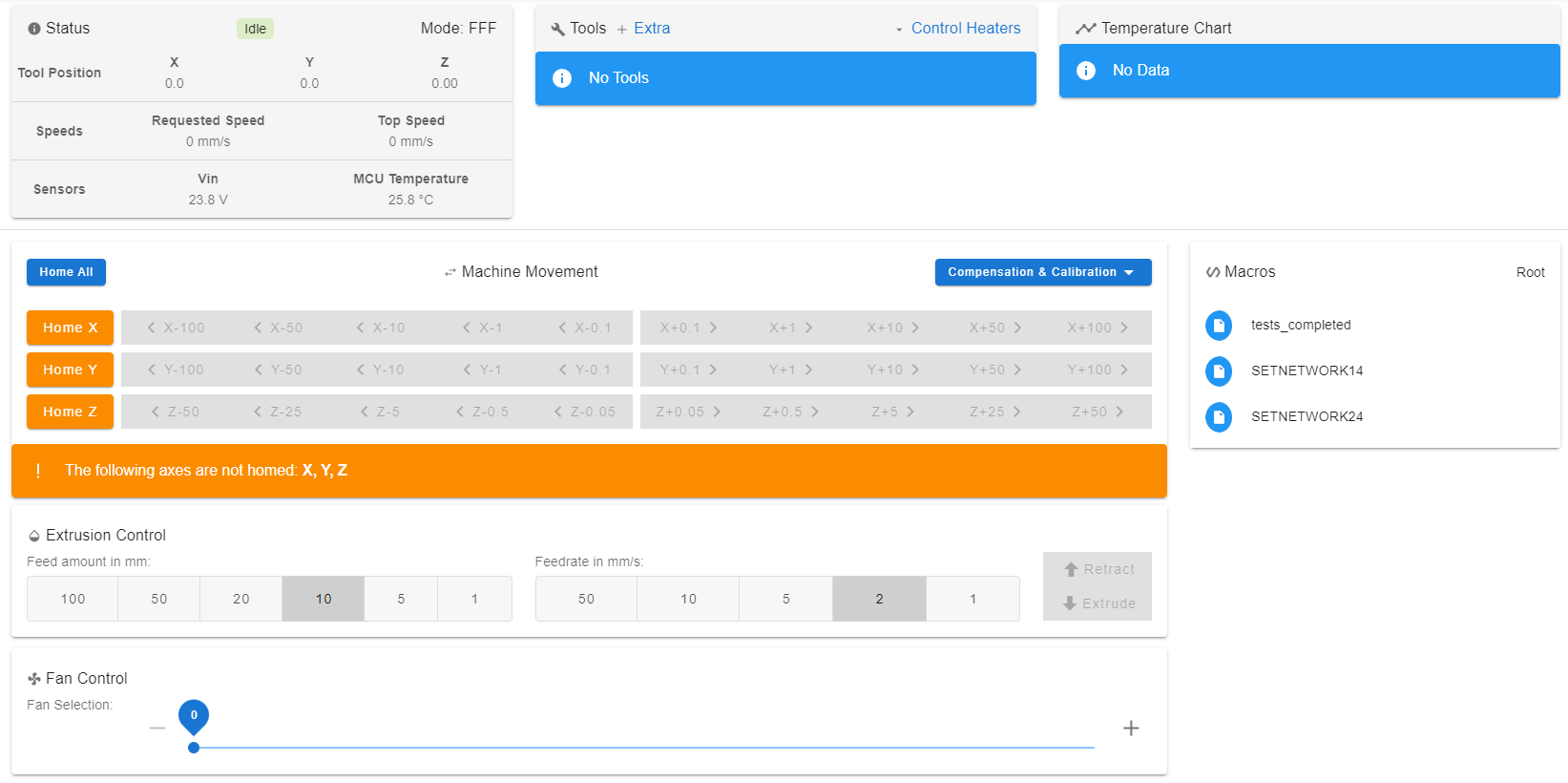
I send it in the console I don't get anything back that I expect like what is shown in step 3. I also don't see any of my tools or anything in my dashboard.
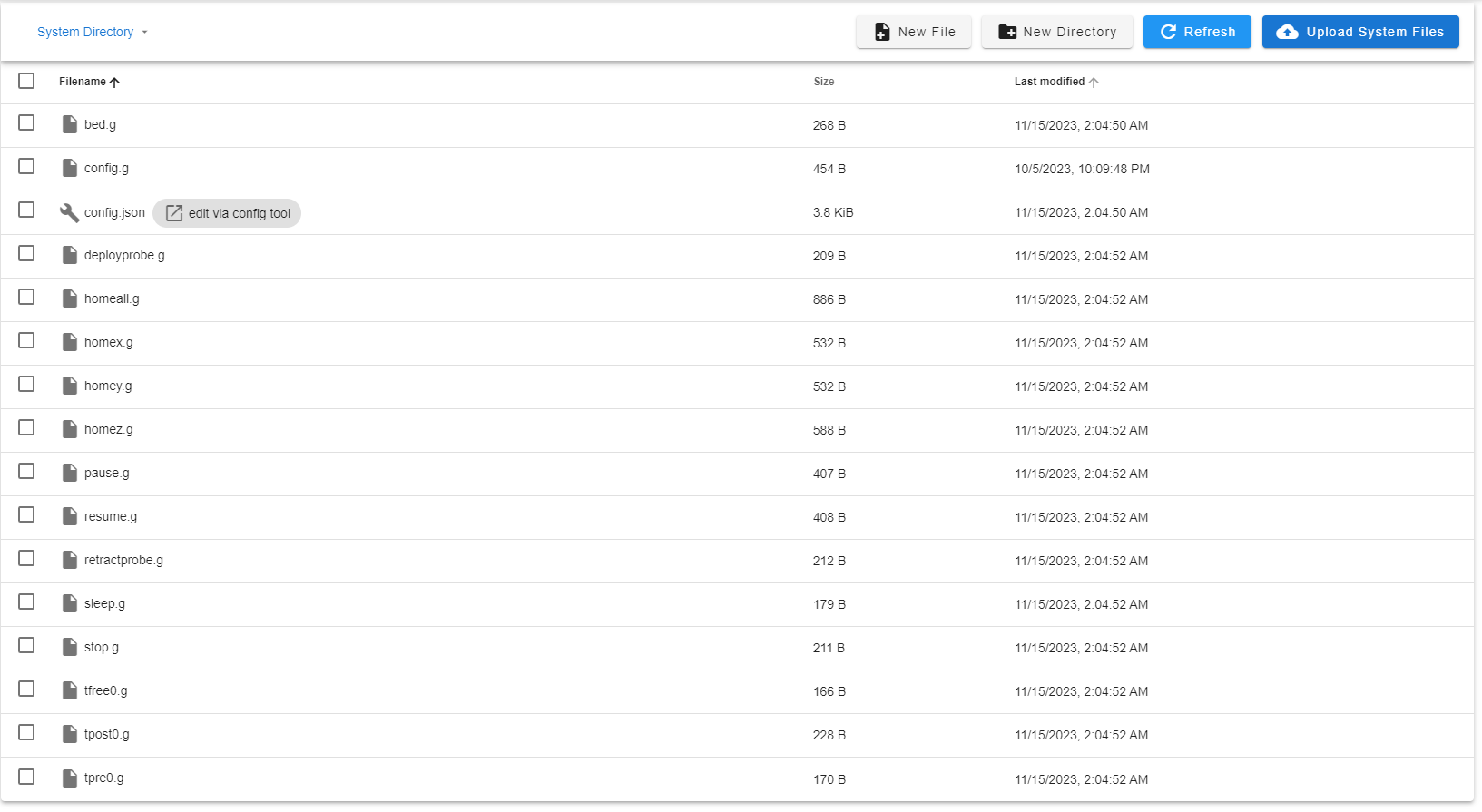
I also have screenshots of my SYS and Firmware folders, they seem to line up with what I expect from the SD Card Document (https://docs.duet3d.com/User_manual/RepRapFirmware/SD_card)
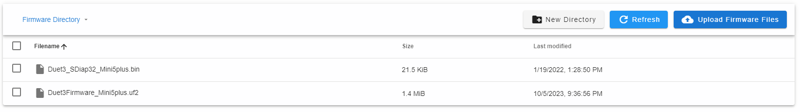
Does this look right and why doesn't my DWC show any information from my printer?
-
@Jman3 in DuetWebConsole, in the sys folder file list, double click on config.g. This should open the config.g that is on the SD card. Copy the text from there and paste it into your reply. Bonus points for putting it in ‘code’ tags (
</>in the toolbar above where you write your reply)!That way I can see what’s in your config.g
Ian
Bed-slinger - Mini5+ WiFi/1LC | RRP Fisher v1 - D2 WiFi | Polargraph - D2 WiFi | TronXY X5S - 6HC/Roto | CNC router - 6HC | Tractus3D T1250 - D2 Eth
-
So it looks like the original config.g that was on the sd card didn't get replaced for some reason and I replaced it with my config.g and everything seems to show up on the DWC now but my stepper motors make a loud teapot whistle noise whenever they are activated.
My situation sounds very similar to this thread but non of the solutions discussed there seem to apply to my printer. (https://forum.duet3d.com/topic/29080/duet-3-mini-5-screeching-noise-when-moving-stepper-motors/2)
Any ideas on why my motors have this issue? The motors seem to move in the correct direction and distance they just make this terrible noise that makes me think something is wrong.
; Configuration file for Duet 3 Mini 5+ (firmware version 3.3) ; executed by the firmware on start-up ; ; generated by RepRapFirmware Configuration Tool v3.3.16 on Tue Nov 14 2023 20:04:52 GMT-0600 (Central Standard Time) ; General preferences G90 ; send absolute coordinates... M83 ; ...but relative extruder moves M550 P"My Printer" ; set printer name ; Network M552 P0.0.0.0 S1 ; enable network and acquire dynamic address via DHCP M586 P0 S1 ; enable HTTP M586 P1 S0 ; disable FTP M586 P2 S0 ; disable Telnet ; Drives M569 P0.0 S0 ; physical drive 0.0 goes backwards M569 P0.1 S0 ; physical drive 0.1 goes backwards M569 P0.2 S1 ; physical drive 0.2 goes forwards M569 P0.4 S0 ; physical drive 0.4 goes backwards M584 X0.0 Y0.1 Z0.2 E0.4 ; set drive mapping M350 X16 Y16 Z16 E16 I1 ; configure microstepping with interpolation M92 X80.00 Y80.00 Z400.00 E93.00 ; set steps per mm M566 X900.00 Y900.00 Z60.00 E300.00 ; set maximum instantaneous speed changes (mm/min) M203 X6000.00 Y6000.00 Z600.00 E3600.00 ; set maximum speeds (mm/min) M201 X500.00 Y500.00 Z200.00 E2500.00 ; set accelerations (mm/s^2) M906 X600 Y600 Z600 E900 I30 ; set motor currents (mA) and motor idle factor in per cent M84 S30 ; Set idle timeout ; Axis Limits M208 X0 Y0 Z0 S1 ; set axis minima M208 X235 Y235 Z260 S0 ; set axis maxima ; Endstops M574 X1 S1 P"io5.in" ; configure switch-type (e.g. microswitch) endstop for low end on X via pin io5.in M574 Y1 S1 P"io6.in" ; configure switch-type (e.g. microswitch) endstop for low end on Y via pin io6.in M574 Z1 S2 ; configure Z-probe endstop for low end on Z ; Z-Probe M950 S0 C"io3.out" ; create servo pin 0 for BLTouch M558 P9 C"io3.in" H5 F120 T6000 ; set Z probe type to bltouch and the dive height + speeds G31 P500 X-44 Y-17 Z2.5 ; set Z probe trigger value, offset and trigger height M557 X20:200 Y20:200 S20 ; define mesh grid ; Heaters M308 S0 P"temp0" Y"thermistor" T98801 B4185 ; configure sensor 0 as thermistor on pin temp0 M950 H0 C"out0" T0 ; create bed heater output on out0 and map it to sensor 0 M307 H1 R2.641 K0.738:0.011 D4.18 E1.35 S1.00 B0 V23.8 ; disable bang-bang mode for the bed heater and set PWM limit, added Tuning here M140 H0 ; map heated bed to heater 0 M143 H0 S120 ; set temperature limit for heater 0 to 120C M308 S1 P"temp1" Y"thermistor" T98801 B4185 ; configure sensor 1 as thermistor on pin temp1 M950 H1 C"out1" T1 ; create nozzle heater output on out1 and map it to sensor 1 M307 H0 R0.314 K0.257:0.000 D4.50 E1.35 S1.00 B0 ; disable bang-bang mode for heater and set PWM limit, added Tuning here M143 H1 S260 ; set temperature limit for heater 1 to 260C ; Fans M950 F0 C"out5" Q500 ; create fan 0 on pin out5 and set its frequency M106 P0 C"Part Cooling" S0 H-1 ; set fan 0 name and value. Thermostatic control is turned off M950 F1 C"out6" Q500 ; create fan 1 on pin out6 and set its frequency M106 P1 C"Heat Block HotEnd" S1 H1 T45 ; set fan 1 name and value. Thermostatic control is turned on ; Tools M563 P0 S"HotEnd" D0 H1 F0 ; define tool 0 G10 P0 X0 Y0 Z0 ; set tool 0 axis offsets G10 P0 R0 S0 ; set initial tool 0 active and standby temperatures to 0C ; Custom settings M204 P600 T2000 ; Set accelerations (mm/s^2) for print and travel moves M912 P0 S-13 ; CPU Temperature calibration M572 D0 S0.35 ; Pressure advance M207 S6.5 R0.0 F2800 T4800 z0.0 ; Retraction M280 P0 S160 ; Clear any alarms M402 ; Retract Pin ; Miscellaneous M501 ; load saved parameters from non-volatile memory M911 S21 R23 P"M913 X0 Y0 G91 M83 G1 Z3 E-5 F1000" ; set voltage thresholds and actions to run on power loss T0 ; select first tool -
@Jman3 Probably nothing wrong, it's just the motor driver is in SpreadCycle rather than StealthChop mode. Some motors whine when in SpreadCycle. You can read about these modes here https://docs.duet3d.com/en/User_manual/Connecting_hardware/Motors_tuning
For a quick fix, put the drivers permanently in StealthChop mode. Change the M569 commands in your config.g to:
; Drives
M569 P0.0 S0 D3 V0                                       ; physical drive 0.0 goes backwards
M569 P0.1 S0 D3 V0                                       ; physical drive 0.1 goes backwards
M569 P0.2 S1 D3 V0                                       ; physical drive 0.2 goes forwards
M569 P0.4 S0 D3 V0                                       ; physical drive 0.4 goes backwards
Then read the above link to work out if that is what you want!
Ian
Bed-slinger - Mini5+ WiFi/1LC | RRP Fisher v1 - D2 WiFi | Polargraph - D2 WiFi | TronXY X5S - 6HC/Roto | CNC router - 6HC | Tractus3D T1250 - D2 Eth
-
@droftarts Thank you so much for the help! I'm printing and things are working well!