CNC Duet3 6XD Omron MX2 VFD forward and reverse
-
Hi everyone,
I am using the Duet3 6XD SBC 3.4.6 as a CNC controller and an Omron MX2 as an VFD. The wiring is as follows:Duet3 6XD MX2 out0 PWM -> 0-10V Converter -> O-Input io5.out.iso -> Input-1 FWD io6.out.iso -> Input-2 RVThe code is
M950 R0 C"out0+io5.out.iso+io6.out.iso" Q1000 L30000The problem is to get the VFD into reverse. When I activate the Spindle in reverse, both, the forward and reverse pins are active.
Do I get the documentation wrong?
M950 R0 C"pwm_pin+forward_pin+reverse_pin" Qfff Laa:bb

    C can have 1, 2 or 3 pins. The first pin defined is a pwm capable pin to set the spindle speed. If a second pin is defined it is used as spindle on/off, if three pins are defined then the second pin is spindle forward and the third is spindle reverse.
In the three-pin setup, there should be one pwm pin, one forward and one reverse, but it turned out that there is one pwm, one on/off and one reverse pin.
I checked the code and this is reflected there
void Spindle::SetRpm(uint32_t rpm) noexcept
{
	if (state == SpindleState::stopped || rpm == 0)
	{
		onOffPort.WriteDigital(false);
		pwmPort.WriteAnalog(0.0);
		currentRpm = 0;						// current rpm is flagged live, so no need to change seqs.spindles
	}
	else if (state == SpindleState::forward)
	{
		rpm = constrain<int>(rpm, minRpm, maxRpm);
		reverseNotForwardPort.WriteDigital(false);
		pwmPort.WriteAnalog((float)(rpm - minRpm) / (float)(maxRpm - minRpm));
		onOffPort.WriteDigital(true);
		currentRpm = rpm;					// current rpm is flagged live, so no need to change seqs.spindles
	}
	else if (state == SpindleState::reverse)
	{
		rpm = constrain<int>(-rpm, -maxRpm, -minRpm);
		reverseNotForwardPort.WriteDigital(true);
		pwmPort.WriteAnalog((float)(-rpm - minRpm) / (float)(maxRpm - minRpm));
		onOffPort.WriteDigital(true);
		currentRpm = -rpm;					// current rpm is flagged live, so no need to change seqs.spindles
	}
}
pay attention to the
onOffPort.WriteDigital(true);in both, forward and reverse branches.If both signals FWD and RV are active, the MX2 is going to stop and to use the 3-wire interface Start/Stop/FWD-RV I need a forth pin in the spindle config.
I'm unable to tell the MX2 to go in reverse, when both FWD and RV signals are present, can someone help me with that?
many thanks
Tim -
I apologize for reheating this thread, I have the same problem with my VFD (Hitachi WF200).
When I run the spindle in reverse, both direction pins on the Duet are active.
Did you find a solution?
-
I don't have direct access to the machine anymore, and I just disabled the reverse function for the cnc.
But i thought about using the 3-wire interface.
It is the same for the Hitachi WF200, you can try to connect the Forward/Active wire to both STA and STP, as STA is active on rising edge and STP is active on falling edge, and connect the Reverse/Not Forward Pin with the F/R pin. I didn't wanted to use edge controlled inputs due to the risk of EMI problems - but it is worth trying.
-
@timschneider we can look at changing the behaviour; however I suspect that we may have implemented it the way you ask originally and then changed it when one or more users reported that their spindles needed on/off and forward/reverse signals.
Duet WiFi hardware designer and firmware engineer
Please do not ask me for Duet support via PM or email, use the forum
http://www.escher3d.com, https://miscsolutions.wordpress.com -
@dc42
Thank you for the opportunity to change the implementation, but I don't have a preference yet. I was just surprised when I did the wiring according to the documentation and wasn't able to put the VFD in reverse.My standpoint right now is, to change the documentation so that it reflects the current implementation and perhaps extend it later with a switch, that will put the logic from OnOff and FW/RV to FW and RV.
Anyhow, I guess the 3-wire interface will also work as explained above, and the EMI concerns are not that big. As what will happen if a surge will hit the OnOff Line, the VFD will go into stop, on the falling edge and right away into run on the rising edge again, so @MaxGyver it's up to you to test that
")
-
@timschneider thank you for your response!
I will test the 3-wire interface tomorrow. Although, my VFD is as far away from the duet as possible in order to avoid EMI. This means running long wires through the whole the cabinet. But it is worth a test:
-
@timschneider
Unfortunately I did not find any information concerning the use of the obove discribed 3-wire interface that works with my VFD.@dc42 All VFD's that I have used so far support the standard dedicated forward and reverse pin inputs. So in order to adhere to the from my perspective comopnly used standard in CNC , a change in the RRF behavoiur would be nessesary.
-
@MaxGyver said in CNC Duet3 6XD Omron MX2 VFD forward and reverse:
Unfortunately I did not find any information concerning the use of the obove discribed 3-wire interface that works with my VFD.
What do you mean by that?
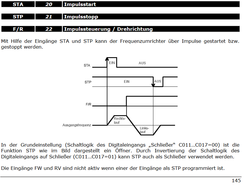
It is described in your manual on page 103
https://www.hitachi-da.com/files/pdfs/produkte/Frequenzumrichter/WJ200/WJ200.pdfYou need to assign the STA, STP and F/R to three different multifunction inputs of your VFD.
duet                  VFD
OnOff ---------------- STA
                   |___STP
FW/RV ---------------- F/R
You can read more about it in the Omron MX2 manual on page 203.
https://assets.omron.eu/downloads/latest/manual/de/i570_mx2_users_manual_de.pdf?v=8 -
Okay this is a bit embarrassing, I have three CNC-Machines all with VFD's from differend manufacturers and therefore different manuals. Turns out I was looking at the wrong manual.

It is all working now . Thank you for your support

-
@timschneider @MaxGyver I think there has been a documentation error regarding forward and reverse, and why seemingly both forward and reverse pins are enabled when you use M4.
In M950, to define a spindle we say
C can have 1, 2 or 3 pins. The first pin defined is a pwm capable pin to set the spindle speed. If a second pin is defined it is used as spindle on/off, if three pins are defined then the second pin is spindle forward and the third is spindle reverse.
example
M950 R0 C"pwm_pin+forward_pin+reverse_pin" Qfff Laa:bbBut in the RRF 3.2 version of M453, we say:
C"aaa+bbb+ccc" Names of the ports used to drive the spindle motor. "aaa" is the PWM port used to control the speed. "bbb" (optional) is the digital port used to turn the spindle motor on. "ccc" (optional) is the name of the port used to command reverse instead of forward spindle rotation.
example
M453 C"exp.heater3+exp.heater4+exp.heater5" Q100 T1 ; spindle PWM on heater 3 pin, on/off on heater 4, reverse/forward on heater 5, PWM frequency 100HzThis second version seems more consistent with the behaviour of the pins - I've just tested, setting bed, e0 and e1heat on a Duet 2 as the three spindle pins (they have LEDs, so I can see when they are on). When I enable the spindle with M3, I get the bed and e0 LED lit (PWM and On), and with M4 I get all three lit (PWM, On, Reverse). The old M453 entry seems to more accurately represent what RRF is doing.
Do your VFDs support this mode of operation?
Ian
Bed-slinger - Mini5+ WiFi/1LC | RRP Fisher v1 - D2 WiFi | Polargraph - D2 WiFi | TronXY X5S - 6HC/Roto | CNC router - 6HC | Tractus3D T1250 - D2 Eth
-
@droftarts said in CNC Duet3 6XD Omron MX2 VFD forward and reverse:
Do your VFDs support this mode of operation?
Short answer: No.
My VFD's have separate input pins for forward and reverse rotation of the spindle. If both pins are active, the spindle will just sequel.
Here is an example of my cheaper 1.5kW Vevor VFD. This configuration will work out of the box without any configuration for pretty much any VFD.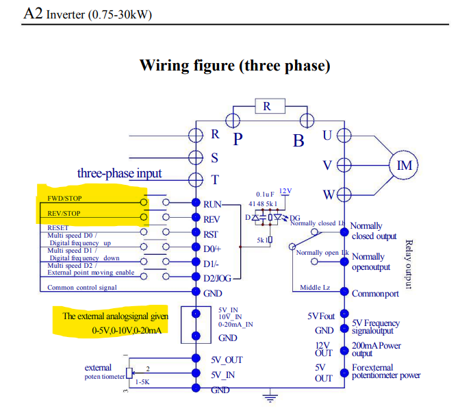
Some (more expensive) VFD's like the Omron MX2 and my Hitachi WF200 support the above-mentioned 3 wire interface. It is meant to be used with pulse signals to start and stop the rotation, and a high or low signal for forward and reverse rotation. The VFD has to be configured accordingly. It took me some time, but I got it working in the end.
-
@droftarts
The description of M453 should in any case be transferred to the M950 spindle mode, as it describes the currently implemented behaviour.@MaxGyver
I think you can change the behaviour of the A2 from FWD and REV to RUN and REV with the paramter P5. It is set to 3 by default, but I guess if you change it to 1 it means RUN and FW/REV.