bed level
-
ok, I succeeded in updating and connecting.
now how can I adjust the bed level?
when I do a G32 (delta calibration) is it consider the differences on the bed while printing?m115
FIRMWARE_NAME: RepRapFirmware for Duet 2 WiFi/Ethernet FIRMWARE_VERSION: 3.4.4 ELECTRONICS: Duet WiFi 1.02 or later FIRMWARE_DATE: 2022-10-20 16:17:41thank you!
-
@kuper See https://docs.duet3d.com/User_manual/Tuning/Delta_calibration
Your bed mesh does look a bit strange. As it seems to be high at the towers and low in between, I would guess it's a combination of incorrect rod length and incorrect delta radius. However, the delta calibration should be able to sort this out and get your bed mesh looking flatter.
Also, you have updated to 3.4.4, but 3.4.6 is the current release. https://github.com/Duet3D/RepRapFirmware/releases/tag/3.4.6
Ian
-
@droftarts hey, thank you.
i updated with seemecnc files https://docs.google.com/document/d/1IQf191FP7EgV8IRpa__jZviF_lfd1jcKVwHD2J7U9pw/editpage 14: "At the web browser control “Dashboard”, select “Delta Calibration” from the drop down menu “Compensation & Calibration” (do not run “Mesh”)"
the photo of the bed is with the old version, I don't see a photo like this now after Calibration(maybe if I run mesh?)
I will check the delta calibration manual
-
@kuper the mesh compensation is a plugin now. Go to Plugins and click start on the selected plugin, and you will get the mesh compensation menu option under plugins.
Ian
-
@droftarts
I mean that in the seemecnc manual, they say not to use a "run mash"after G29
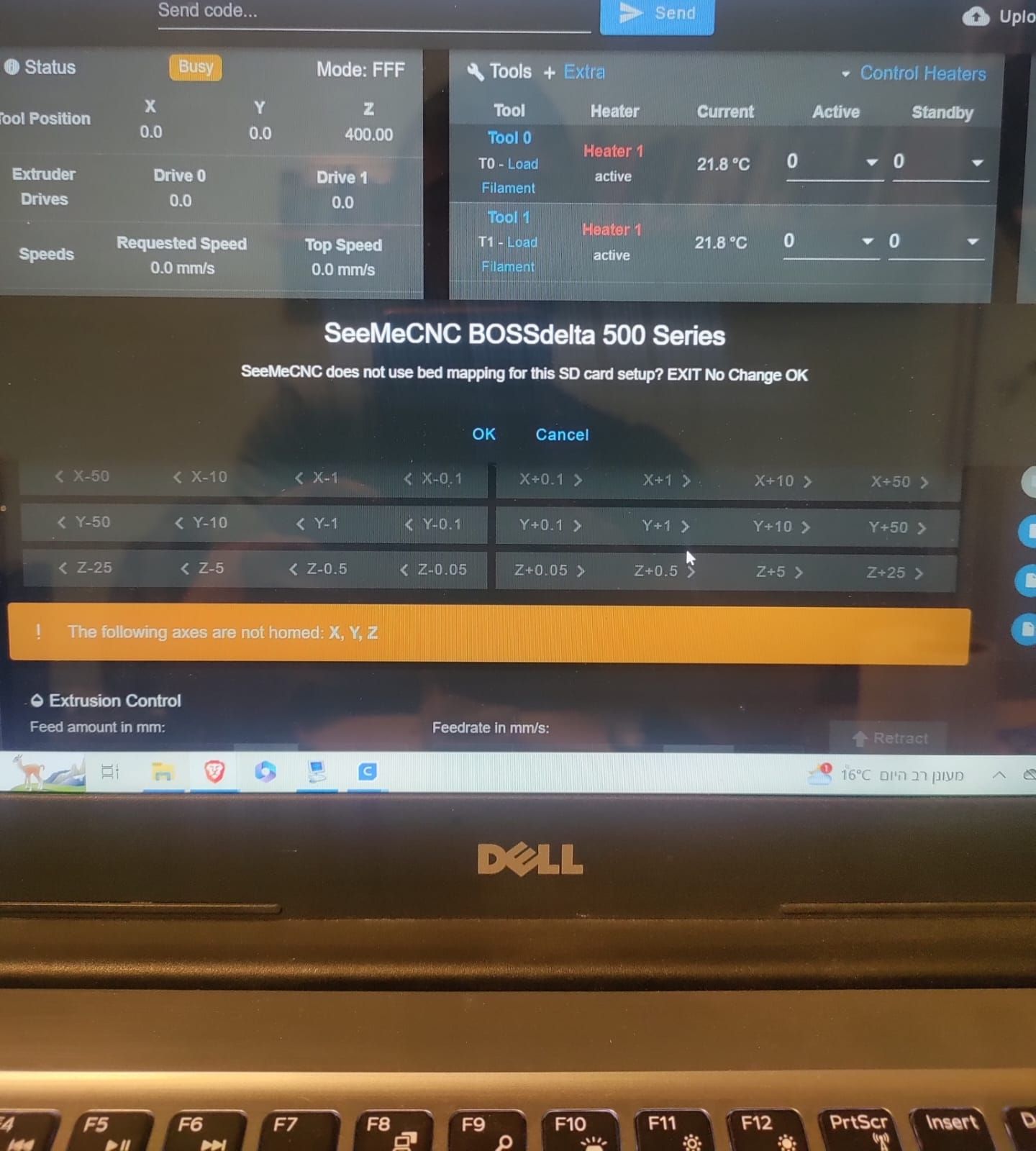
plugins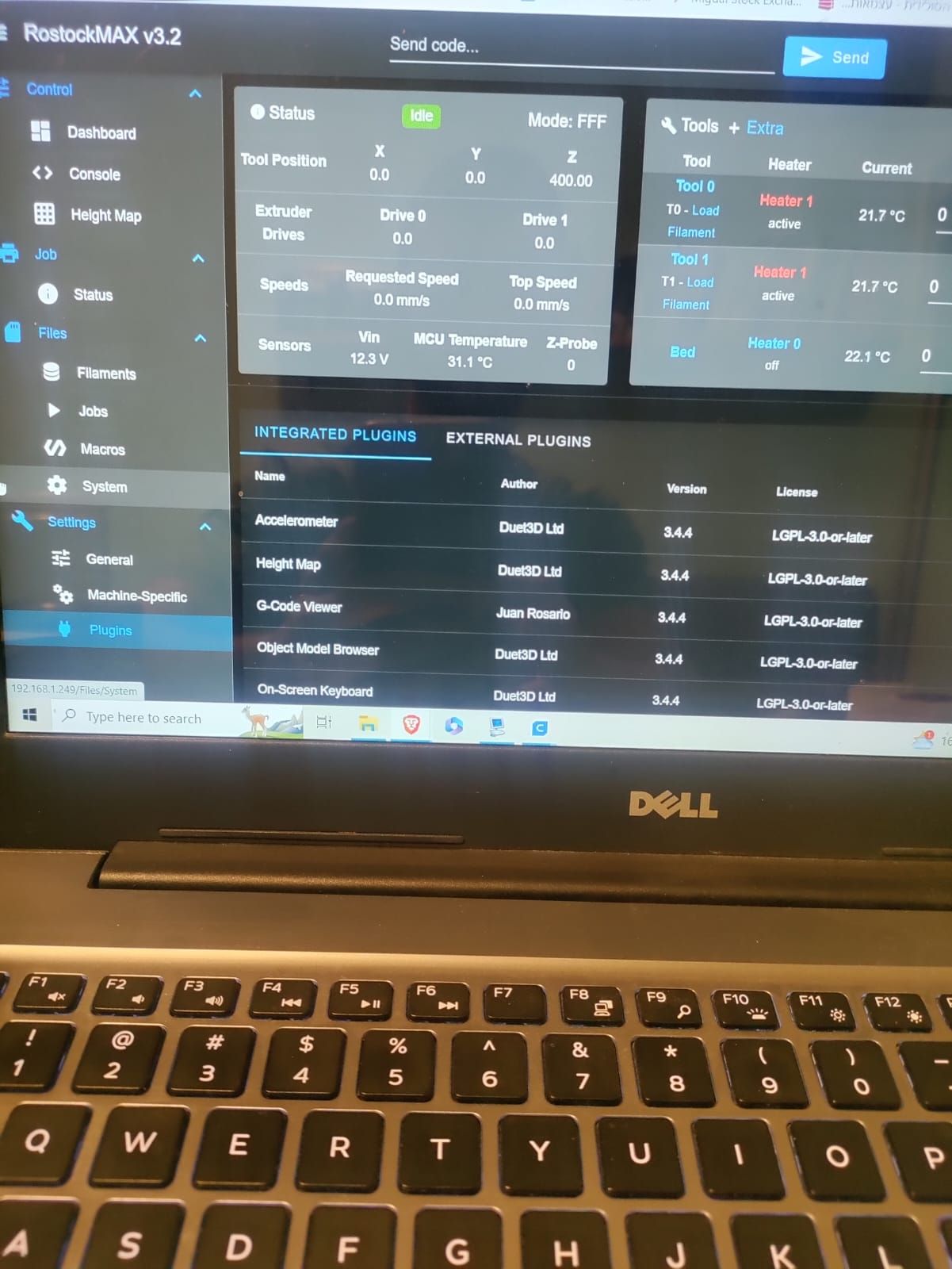
bed map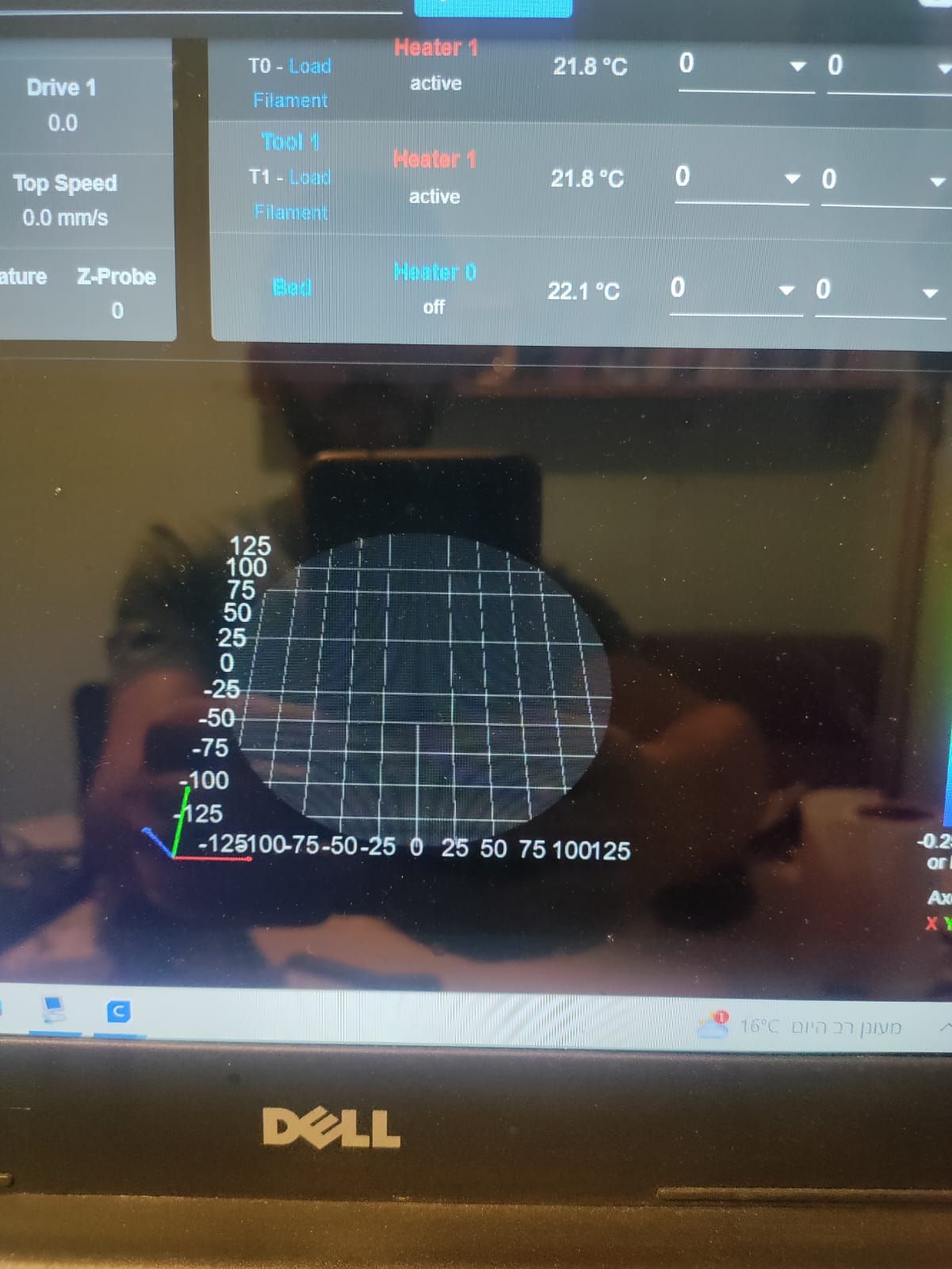
-
@kuper okay. Delta calibration should be in the drop down list in the bed mesh plugin, still.
Ian
-
@droftarts Sorry, didn't get you...
in the plugins, there is no bed mesh...
and when I ran G29 I got the first image "seemecnc does not use bed mapping..."" -
@kuper Sorry, I've been running 3.5 betas for so long I've forgotten where everything is in older versions! I also don't know if the versions of RRF and DWC that SeeMeCNC supplies are custom versions, with Delta Calibration and Mesh Compensation removed. There certainly shouldn't be any issue running these; I do on my Delta.
It looks like you have the 'Height Map' option under 'Control'. The 'Compensation and Calibration' menus is just above the axis jogging buttons, on the 'Dashboard':
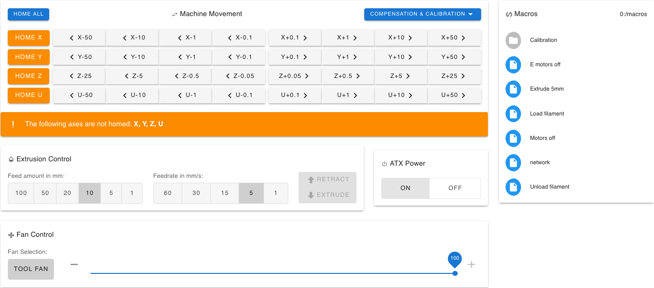
Clicking on that on a Delta should give you this menu:
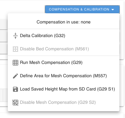
It's a quick way to run the Delta Calibration, ie G32.I think the message is not saying you can't use it, just that there's no bed mesh yet. Clicking OK will probably start a bed mesh probe.
Ian
-
from the seemecnc menual
-All SeeMeCNC Delta’s no longer use mesh (bed map) calibration as of November 2022.
-The “Delta Calibration” now automatically deletes config-override.g and heightmap.csv files, then runs the Delta Calibration routine. There is no longer a need to manually delete files.-"SeeMeCNC continues to NOT use bed mapping. It should not be necessary.
Calibration is only G32, or wavy icon on touch screen, or web control dashboard “Delta Calibration” drop box (middle screen)"after G32
after this G32 calibration, does the printer consider the deviation on the bed?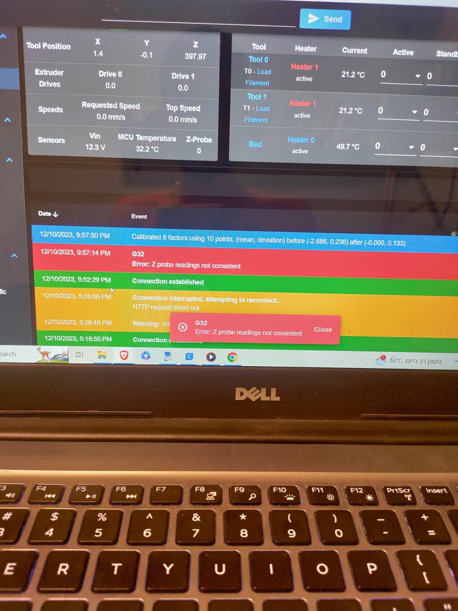
bed mapping Is empty
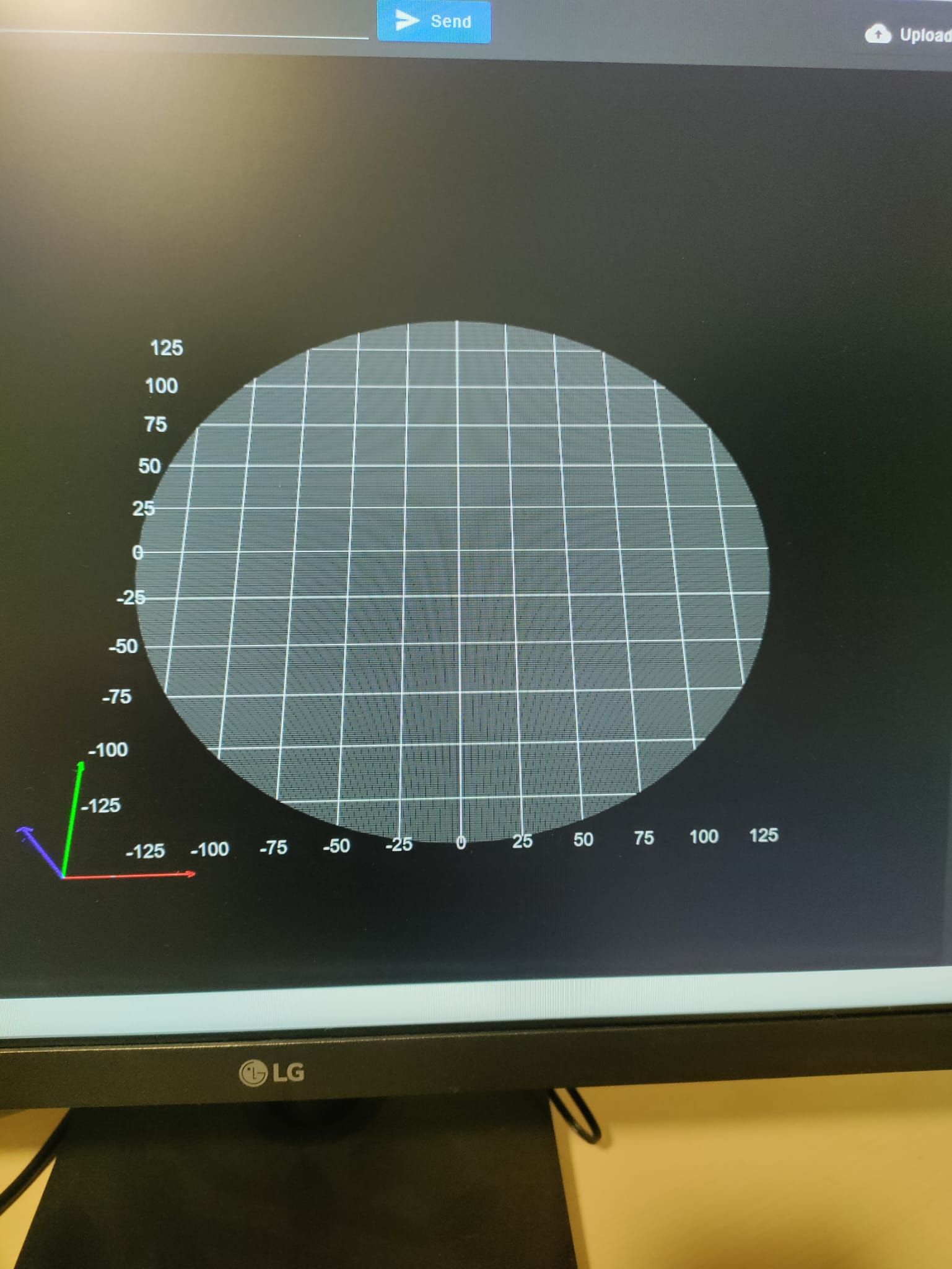
after I G29 it says "seemecnc does not use bed mapping.."
I press ok and nothing, the bed mapping doesn't work.from the seemecnc manual:
RostockMAX v3.2
Edit the config.g file items below, save and power cycle your printer
M665 Arms length and type
M569 Motor Direction - if G28 sends the hot end towards the bed, you’ll need to reverse the setting - If they’re set “S0”, set to “S1” to reverse direction and vice-versa. Check that extruders are turning in the correct direction as well.
M92 Stepper motor AND pulley number of teeth
Early machines had 20T timing pulleys, adjust the steps/mm accordingly
Late model machines have 16T timing pulleys
You also need to consider 1.8deg early model or late model 0.9 degree steppers
M558 Probe Settings (we did not ship FSR bed sensors in this printer model)I don't know if I need to change something in the config file.. and I don't know the parameters of the printer.
I also posted about it in the seemecnc forum.
thank you!
-
@kuper I found the files you are using on Google Docs here: https://drive.google.com/drive/folders/1JviX5yzD6acl_vfEj_9GN0b4aT0D5EpW
It looks like this comes from 'mesh.g' in the /sys folder, which is run when command G29 is sent:; As of Oct 31, 2022, SeeMeCNC does not use bed mapping ; M291 P"SeeMeCNC does not use bed mapping for this SD card setup? EXIT No Change OK" R"SeeMeCNC BOSSdelta 500 Series" S3I'm not sure why SeeMeCNC have disabled mesh compensation; it's a useful tool for working out if there is an issue with the bed. It may be they feel the bed is physically flat enough, and that delta calibration does a good enough job of fixing any other problems, and mesh compensation just adds a level of complexity. You can override this; if you change the name of mesh.g in the /sys folder to something else, eg no_mesh.g, then it will run mesh compensation as usual. The correct commands are in the config.g for it to work with (
M557 R130 S30 ; define mesh grid).I don't know if I need to change something in the config file.. and I don't know the parameters of the printer.
If the delta calibration completed successfully, and you can run a test print, I'd guess that you have the standard arms, the motors move the right way, the number of teeth are correct, and so are the motors. To get 200 steps per mm (M92 X200 Y200 Z200 in config.g) I'd guess you have 0.9° motors (it usually says on the back of the motor), 16x microstepping (M350 X16 ... in config.g), with 16T pulleys (count the teeth), using GT2 belt with a belt pitch of 2mm (measure the distance between a number of teeth on the belt, divide by the number of teeth, the answer should be 2mm). Maths:
steps_per_mm = (motor_steps_per_rev * driver_microstep) / (belt_pitch_mm * pulley_number_of_teeth)
(400 * 16) / (2 * 16) = 200
A quick test is to move in Z 100mm, which moves all three motors, and measure if they did actually move 100mm.If you kept a copy of your old config.g from before you updated, that will tell you the settings it was using.
The 'Error: Z probe readings not consistent' is a bit worrying. Try running Delta calibration a second time, and see if it says the same thing again. Otherwise, the 'after (-0.000, 0.133)' response from the calibration is pretty good.
Ian
-
@droftarts thank you for helping!
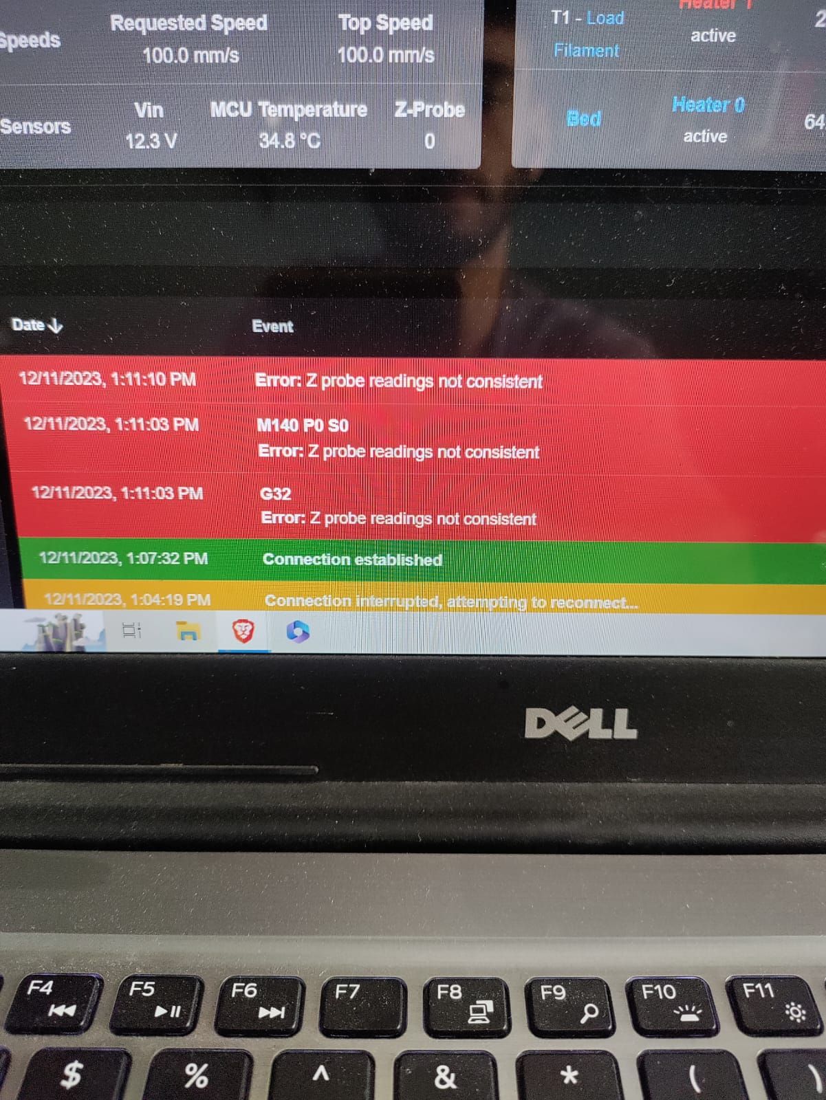
yeah, the dimensions are standard and I printed already but I have some issues with the bed leveling.I changed the mesh file to no_mesh and it is running now but it stopped during the mesh compensation because of the z probe problem...
I tried to run delta calibration several times and still, I have a z-probe error.
-
@kuper I think your bed probe is the PCB that the hot end is connected to, which acts as a strain gauge: see https://www.seemecnc.com/products/se300-v1-4-probing-circuit-board
If you are getting inconsistent probe readings, I think you should post on the SeeMeCNC forums and get support from them to help resolve it, as I don't have access to or experience with this hardware. It will effect the delta calibration and bed mesh if it not reporting accurately.
Some general advice with these kinds of probe: make sure the nozzle is bolted down firmly to the PCB, and that all parts of the nozzle are tightened up correctly (see the build guide here https://seemecnc.dozuki.com/Guide/SE300+Build+Guide/94). Make sure the nozzle is clean before probing, ie no bits of filament stuck to the nozzle, or oozing.
Also, your probe settings, from the SeeMeCNC supplied config, are:
M558 P5 I0 A4 R0.4 C"zprobe.in" H20 F2500 T6000         ; HOTEND PROBEset Z probe type to switch and the dive height + speeds
G31 P500 X0 Y0 Z-0.35                                    ; set Z probe trigger value, offset and trigger height
See M558 for the meaning of the parameters. I think
I0is incorrect; it should beK0, for the probe number. In RRF, incorrect parameters are just ignored, rather than triggering an error.
The A4 parameter means that for each probe point, it tries up to 4 times to get a reading that is within the set sensitivity. In this case, it is using the default of 0.03mm, as there is no S parameter. It could be this that is giving the inconsistent readings. You can do a probing test by running this macro:; ProbeTest.g ; Create a new macro, copy and paste this into it, then run it G28 G30 P0 X0 Y0 Z-9999 G30 P1 X0 Y0 Z-9999 G30 P2 X0 Y0 Z-9999 G30 P3 X0 Y0 Z-9999 G30 P4 X0 Y0 Z-9999 G30 P5 X0 Y0 Z-9999 G30 P6 X0 Y0 Z-9999 G30 P7 X0 Y0 Z-9999 G30 P8 X0 Y0 Z-9999 G30 P9 X0 Y0 Z-9999 S-1Which will give results something like:
M98 P"0:/macros/ProbeTest.g"
G32 bed probe heights: 0.045 0.046 0.047 0.047 0.046 0.047 0.048 0.048 0.047 0.047, mean 0.047, deviation from mean 0.001
Lastly, no need to take pictures of your screen. You can highlight any text in DWC, then copy and paste it into your reply!
Ian