Help with component identification
-
@moth4017 They both had 3 legs, the corrosion removed the third. I've looked
all over for that logo and the markings and I can't find anything definitive. I'm seeing this
more lately where i'm trying to fix a device but the markings on components dont lead anywhere. If I could find a broken one of these cameras on ebay, I might go that route unless someone has some insight here. Thanks for your interest! -
@Idodgeads they are most likely BJTs or mosfets. You could use a multimeter to check which leads register diodes between them and measure the forward voltage, to tell which.
-
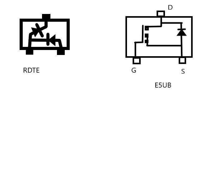
This one has E5* marking code, but I would try to confirm by measurement as dc42 said.
https://www.s-manuals.com/pdf/datasheet/s/i/si2335ds_vishay.pdf
-
@dc42 Thanks everyone for the help. I wasn't sure if this would get much attention since it is a bit off topic. Preventing the burning down of one's house is a noble endeavor. I went through this with my duet 2 wifi board as it was purchased used and abused. Multiple fried components, things didn't work. I was able to fully restore the board with the help of reading this forum.
I was wondering if an LCR meter would be of any help here? I don't know the scope of what components those meters will identify or identify correctly. I'm sure caps, resistors, diodes and the usual stuff but what about zeners and more complex fets and things?
I may order one if I can find a way to get leads attached to the components
to test them. Missing one leg on each isn't going to help matters....maybe the
use of a needle as a probe? -
@Idodgeads, a simple multimeter, even a very cheap one, will be able to measure what @dc42 suggested.
As for accessing the broken terminals, can you see any part of the broken terminal? If not, can you scrap/file gently around it to have minimal access?
If you want to try something new, you can buy on Aliexpress and other places an electronic component identifier. You connect a two or three leads components and it identifies the type and the pinout. Not perfect but amazingly good for the money.
-
@zapta I think I can make contact with what's left of the terminals. They're broke off flush
but they are there. I ordered the T7 tester, it should be here next week. I hope the tester will take the guess work out of this project. I'll report back when I get the results. -
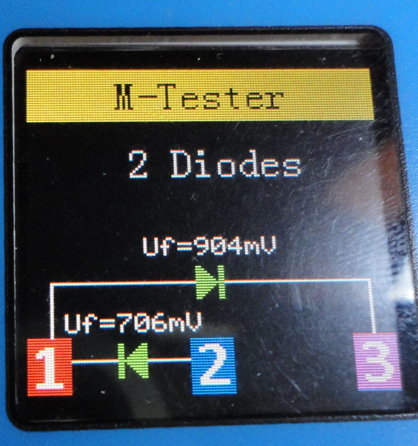
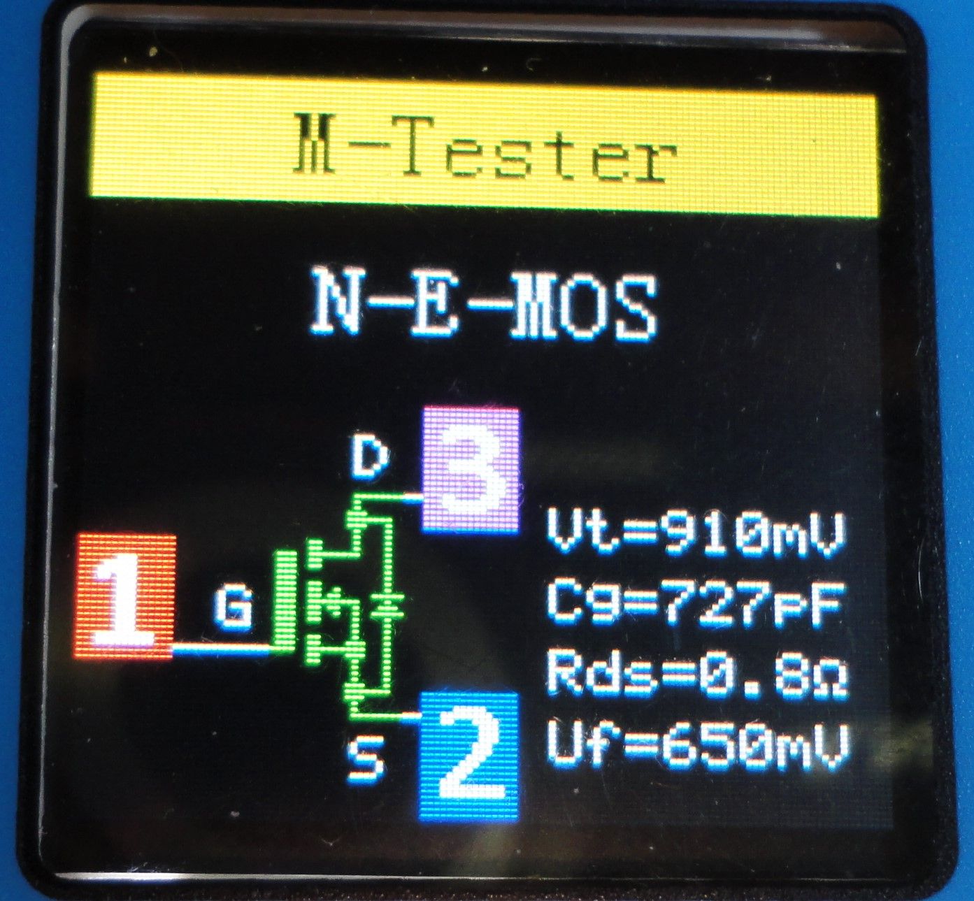
@zapta So it took longer than expected to get the tester but here's what I got.
I don't think the tester is very good with zener diodes. It has 3 terminals just for those but if you connect a standard diode there and test, it shows it as a zener as well. With that said, I think RDTE could be a duel zener...I just don't know how to tell. Finding suitable replacements is where I need help.


-
@Idodgeads you most likely have nothing to loose now so try a GP n channel mosfet
like https://www.farnell.com/datasheets/2861336.pdf -
@moth4017 Thank you! That fills in the blank for the mosfet, now I have to figure out
the other component. I may reach out to the company for a schematic. My chances are slim
but its worth a try. I can't find a dual zener diode with that configuration. It could be my new tester is lying to me and it's something completely different.Thanks again,
-
@Idodgeads why do you think they are zener diodes rather than ordinary diodes?
-
@dc42 Its just the inconsistency of the tester I have. I found on one of the databases
the RDt component is listed as a dual zener diode but my tester does not show it in a
configuration I can find to purchase. This confuses me. I contacted the company, they won't help other than replace the unit with proof of purchase and evidence of the corrosion. Well, I already removed the corrosion in my first repair attempt. The proof of purchase I doubt I can find sadly. -
@Idodgeads, as @dc42 said, they can be diodes. The difference between 'diodes' and 'zeners' is that the zeners are intended to operate at their breakdown voltage.
You can test the breakdown voltage using a power supply (same voltage as the target circuit) and a resistor. Connect the diode in series to a resistor (e.g. 10K) to your power supply such that the diode gets reverse voltage (+ on the cathode, - on the anode) and measure the voltage across the diode. If the voltage on the diode is significantly less than the power supply than this is the voltage rating of the zener, otherwise, it's most likely a diode.
To test zeners, the tester needs to have voltage higher than the zener breakdown voltage and I think this tester is limited to 5V. Same with most digital voltmeters which tests diodes but not zeners.
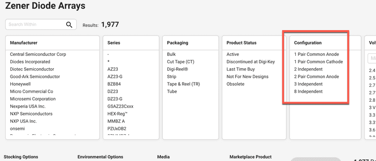
Looking at Digikey, I don't see a zener array with the arrangement you mentioned.

-
@zapta I have nothing else to do today so this will be my goal. I really hope after all the trouble, it's not something else wrong with the camera entirely lol.
Thanks for the help. -
@zapta For those who may be curious how this turned out, I was not able to discern what type of component I needed to replace. I did the manual check
for zener diodes and that test did not show a zener diode. The T7 tester I bought for this is also confused. It has shown IGBT, PD mos, dual diodes and cross connected diodes. It's not consistent at all with this one component. I asked a person I know that use to repair tv's and he said it could be a custom part made just for that company. This might explain why the markings don't
show up anywhere. Anyway, I found my receipt and the company replaced the faulty unit. Thanks to everyone that chimed in, I promise not to burden the forum with this sort of thing in the future.