Duet3D Logo Duet3D
    • Tags
    • Documentation
    • Order
    • Register
    • Login

    Connecting a BLDC Controller to Duet Mainboard 6HC

    Scheduled Pinned Locked Moved
    Duet Hardware and wiring
    4
    10
    368
    Loading More Posts
    • Oldest to Newest
    • Newest to Oldest
    • Most Votes
    Reply
    • Reply as topic
    Log in to reply
    This topic has been deleted. Only users with topic management privileges can see it.
    • SANJRundefined
      SANJR
      last edited by SANJR

      Greetings,

      I am trying to connect a brushless DC motor with its controller (BLD750) and control the PWM by Duet Mainboard 6HC (OUT 5). A simple schematic of the same is attached below for reference.

      Second Feeder Wire.png

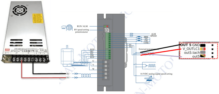
      In the config.g file the motor is configured as shown below

      ;fans
      M950 P5 C¨out5¨ Q250  ; Allocate GPIO port 5 to OUT_5 (fan output), 250Hz
      

      And two macro files for ON and OFF operation of the motor

      ; DC Motor ON
      M106 P5 S255    ; Turn on the motor at full Speed
      M42 P5 S0.5     ; Set 50% PWM on GPIO port 5
      
      ; DC Motor OFF
      M106 P1 S0      ; Turn off the Motor
      

      Does the circuit and G Code files fulfill the requistite? Any modification or improvements would be appreciated.

      Thanks in advance

      janjohundefined droftartsundefined 2 Replies Last reply Reply Quote 0
      • janjohundefined
        janjoh @SANJR
        last edited by janjoh

        @SANJR I would personally not draw this as "replacing the resistor", yes, they all use the sam control input but it just looks odd. Also keep in. mind that the fan connectors use low side switching (as you normally do). They are not high side switching.

        You should consult page 5 in the documentation for the driver. This is what I would use;

        "Motor Speed Adjusted By Pulse Rate Input:
        Pulse rate: 0K—3KHZ Speed linear modulation
        Pulse amplitude: 5V Pulse duty ratio: 50%
        SW1/ On (User setting) RV—Turn Off
        J7 (Internal)/ Switch on with the jumper cap on J1 (User setting)"

        o_lampeundefined SANJRundefined 2 Replies Last reply Reply Quote 1
        • droftartsundefined
          droftarts administrators @SANJR
          last edited by

          @SANJR said in Connecting a BLDC Controller to Duet Mainboard 6HC:

          M950 P5 C¨out5¨ Q250
          

          It looks like you are using strange quote marks (they look more like dots) than straight quote marks.

          M950 P5 C"out5" Q250
          

          Ian

          Bed-slinger - Mini5+ WiFi/1LC | RRP Fisher v1 - D2 WiFi | Polargraph - D2 WiFi | TronXY X5S - 6HC/Roto | CNC router - 6HC | Tractus3D T1250 - D2 Eth

          SANJRundefined 1 Reply Last reply Reply Quote 1
          • o_lampeundefined
            o_lampe @janjoh
            last edited by

            @janjoh Although I agree with you, I'd like to know how to achieve that on the Duet side?
            How do you send a gcode with static 50% duty cycle, but variable frequency?

            It would be helpful to have a Q-parameter in M106, like M106 P5 S0.5 Q3000
            #firmware wishlist ?

            janjohundefined 1 Reply Last reply Reply Quote 1
            • janjohundefined
              janjoh @o_lampe
              last edited by

              @o_lampe Oh fair point. Yeah, so in this case PWM to acheive 0-5V probably is what will happen.

              o_lampeundefined 1 Reply Last reply Reply Quote 1
              • o_lampeundefined
                o_lampe @janjoh
                last edited by

                @janjoh @SANJR It's worth a try, but I'd go for a higher base frequency than 250Hz and use P5 in the macro not P1 as you did in your example...

                janjohundefined SANJRundefined 2 Replies Last reply Reply Quote 0
                • janjohundefined
                  janjoh @o_lampe
                  last edited by

                  @o_lampe Actually, I think you tagged the wrong person there?

                  1 Reply Last reply Reply Quote 0
                  • SANJRundefined
                    SANJR @janjoh
                    last edited by

                    @janjoh

                    Thanks JANJOH

                    I have a few questions. As suggested gone through the page 5 of this driver manual. And were able to understand the on how to control the motor speed by the pulse rate input.

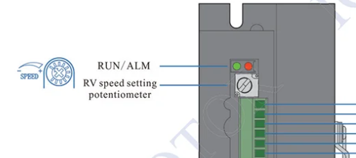
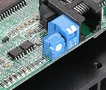
                    The RV Internal Potentionmeter (Image shown below)at the side of the driver has to be set off if a signal is given from control, in our case duet control board.
                    RV Internal Potentionemeter.png

                    Both the switched are set to ON condition. Each has the below functions,
                    SW1 -> ON - Pulse Rate Input (User Setting) and
                    SW2 -> ON - Quick Speed Response (User Setting) is to be ON.
                    BLD Top View.png

                    However the Jumper 7 and Jumper 1, I am not able to infer. Any idea on how to find out these Plz?

                    Any my understanding of statement "replacing the resistor" is vey much limited? Can u elucidate what it means? (My understanding of electrical and electronics is limited......)

                    1 Reply Last reply Reply Quote 0
                    • SANJRundefined
                      SANJR @droftarts
                      last edited by

                      @droftarts

                      Noted. Thanks for the reply.

                      Will change the quote marks

                      1 Reply Last reply Reply Quote 0
                      • SANJRundefined
                        SANJR @o_lampe
                        last edited by

                        @o_lampe

                        Thanks

                        Will update the same

                        1 Reply Last reply Reply Quote 0
                        • SANJRundefined SANJR referenced this topic
                        • First post
                          Last post
                        Unless otherwise noted, all forum content is licensed under CC-BY-SA