Duet 3HC Expansion looses Connection
-
@infiniteloop said in Duet 3HC Expansion looses Connection:
@developeralgo222 said in Duet 3HC Expansion looses Connection:
i will try another cable
Great

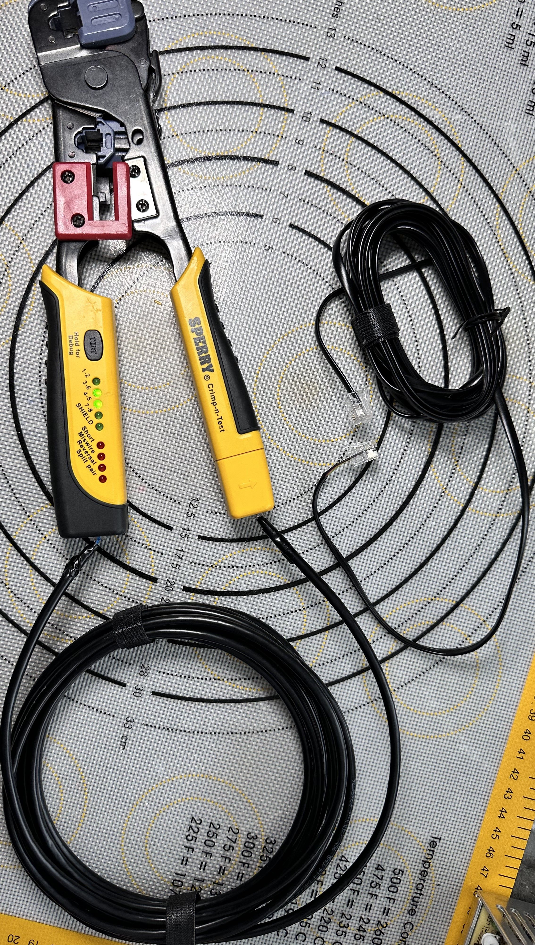
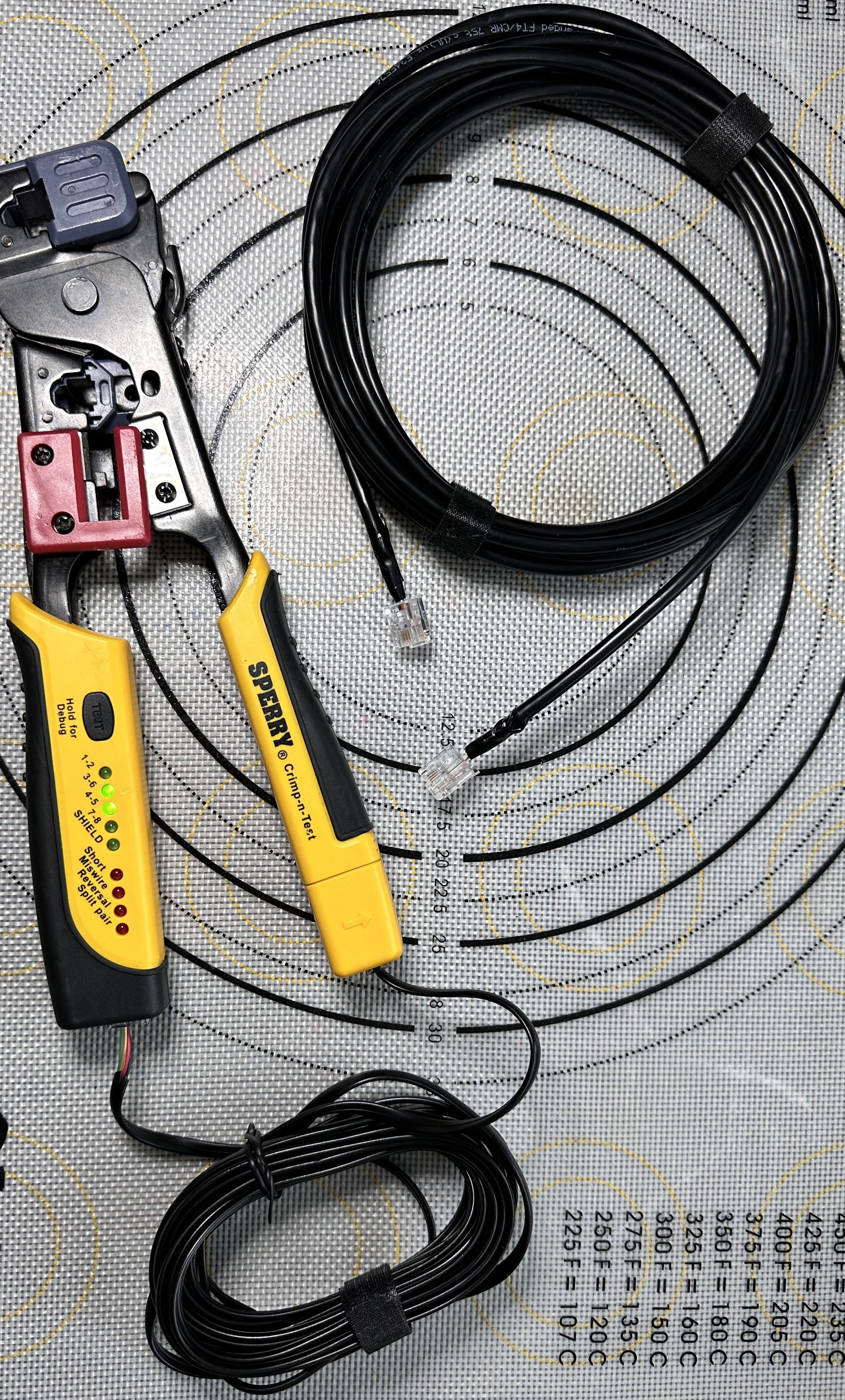
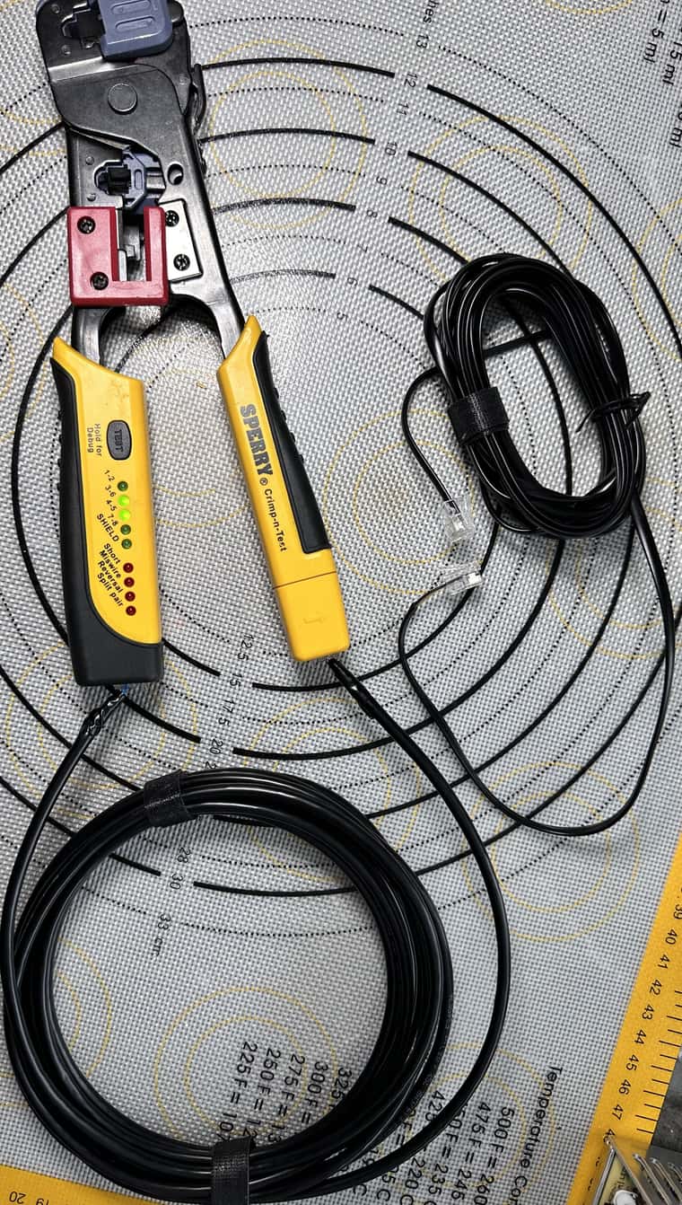
Made 2 different straight cables which are shielded and 1 std phone cable (Normally crossed, so i cut one end and crimped it to straight cable ).
Cable 1 - Made from CAT 6 Cable (using only 2 pairs for CAN Bus --technically on 2 wires are used) and RJ11 at the ends
Cable 2 - Made from CAT 8 Cable (using only 2 pairs for CAN Bus --technically on 2 wires are used) and RJ11 at the ends
Cable 3 - Made from Std Phone Cable (using only 2 pairs for CAN Bus --technically on 2 wires are used) and RJ11 at the endsAll of them behaved the same when testing each of the 4 x 3HC boards with nothing connected to them only power.
6XD --> Board 1 (with CAN Jumpers) CAN_IN / CAN_OUT -- Sync
6XD --> Board 2 (with CAN Jumpers) CAN_IN / CAN_OUT -- No Sync
6XD --> Board 3 (with CAN Jumpers) CAN_IN / CAN_OUT -- No Sync
6XD --> Board 4 (with CAN Jumpers) CAN_IN / CAN_OUT -- No Sync
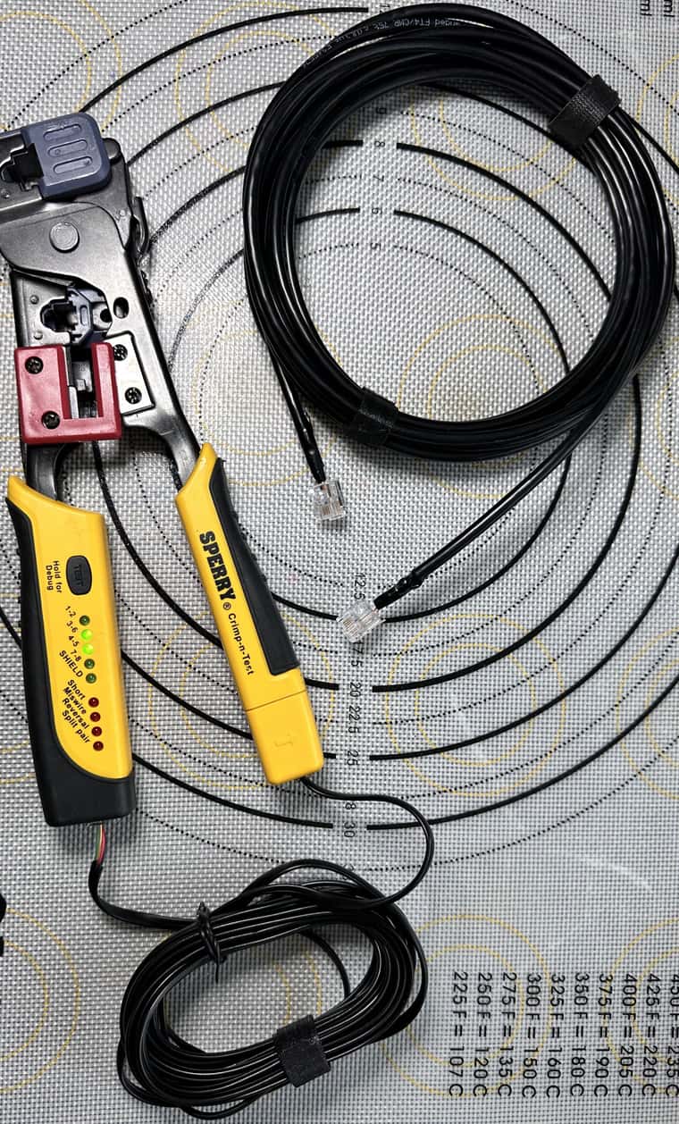
Not sure why CAN Bus would be this unreliable. For sure i checked the cables , tested them using a different cable tester ( Sperry ) this time to rule out anything. i don't think its the cables after this round of tests
-
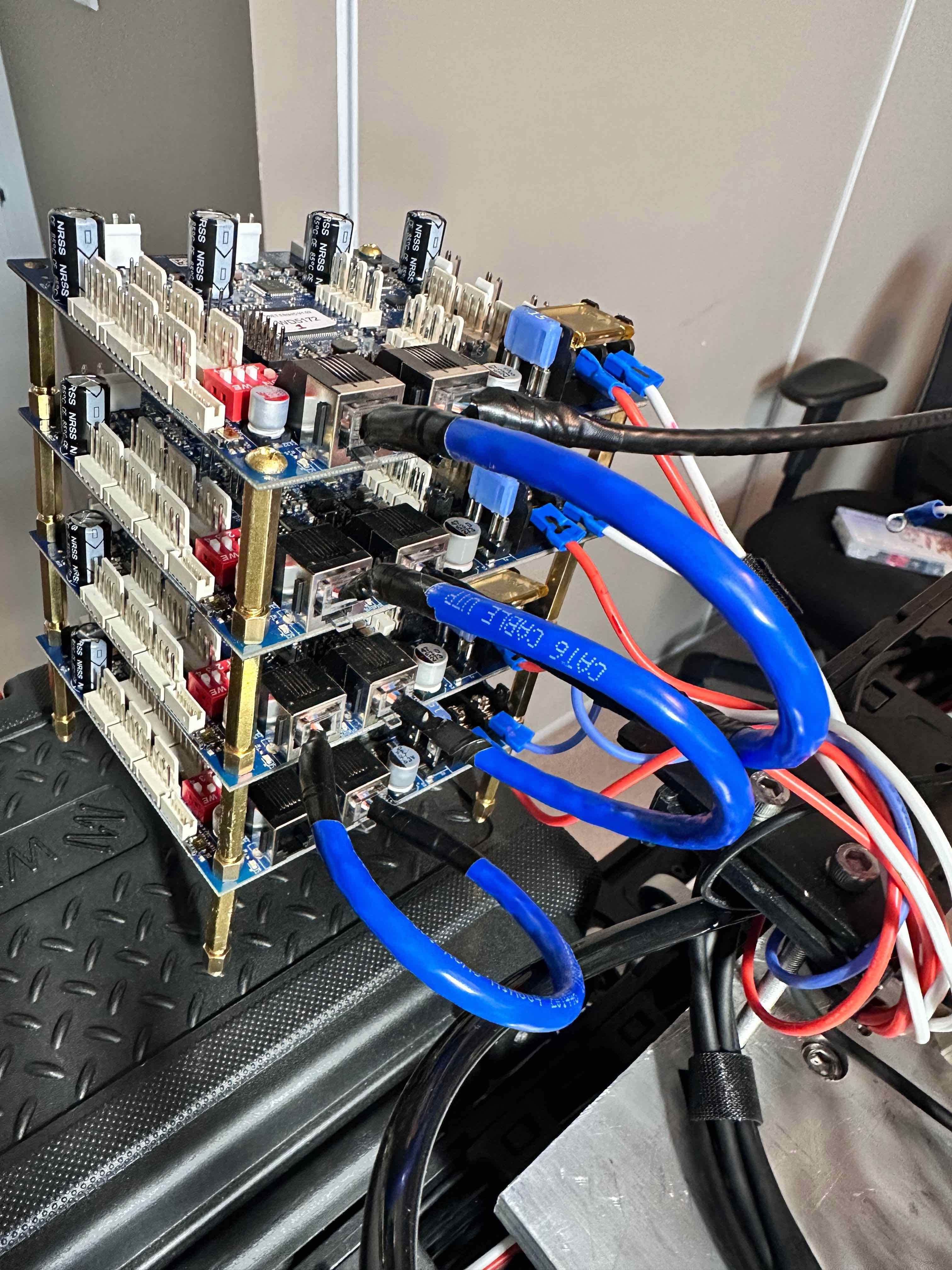
@developeralgo222 something to do with the mounting? You have them stacked, using what looks like electrically conductive standoffs. I don’t know if that connects the grounds of the boards at a point that causes problems, rather than at the PSUs. You could try powering all four boards (or all boards) from one PSU, see if that makes a difference.
Ian
-
@droftarts said in Duet 3HC Expansion looses Connection:
@developeralgo222 something to do with the mounting? You have them stacked, using what looks like electrically conductive standoffs. I don’t know if that connects the grounds of the boards at a point that causes problems, rather than at the PSUs. You could try powering all four boards (or all boards) from one PSU, see if that makes a difference.
Ian
Hmmm!!! i don't think so unless the boards themselves have Power rail circuit layer (copper) touching the mounting holes . That would be really really bad. When i did the Test setup they were separated (Not mounted) although still on Brass standoffs. Your thought might be something to investigate , i will check that and try Nylon standoffs
-
@developeralgo222 said in Duet 3HC Expansion looses Connection:
Not sure why CAN Bus would be this unreliable.
It's not about CAN - I've built several applications for constructing machinery from the ground up, connecting controllers via CAN, and these connections are rock-solid. This said, I am now convinced that we can rule out your CAN wiring as cause of the problem. Which leads me to believe we might face an effect which I described as "interesting" early on: some interference between GND and Earth.
In your test setup, the boards were strictly isolated from Earth (which was just connected to the two PSUs). Earth is received from the electrical outlets and internally connected with the metal cases of the PSUs. In addition, the metal parts of you PnP machine should be "earthed" as well. The one million dollar question now is: have GND and Earth any potential contact? Or are they maybe decisively synced somewhere?
The latter case is something I've done myself, but is not without pitfalls, so I'd like to ask @droftarts for a second opinion. At least, he's on the same trail …
-
@infiniteloop said in Duet 3HC Expansion looses Connection:
@developeralgo222 said in Duet 3HC Expansion looses Connection:
The one million dollar question now is: have GND and Earth any potential contact? Or are they maybe decisively synced somewhere?The latter case is something I've done myself, but is not without pitfalls, so I'd like to ask @droftarts for a second opinion. At least, he's on the same trail …
Today, I have isolated all the PSUs and all are “Earthed” ( AC Ground ) . They don’t touch the aluminum metal table at all anywhere. I will also “Earth” (AC ground ) the aluminum metal table today.
Is there anything I might be forgetting on this GND solution. I am trying to avoid creating GND loops
-
Is there anything I might be forgetting on this GND solution. I am trying to avoid creating GND loops
That’s complex. As a general rule, imagine a star topology, I.e. for each and every voltage, there should be a single point (or rail) from where to further route the power lines.
For your dual PSUs, you already have this central point: V+ (1 rail with 3 connectors on each PSU) is now interconnected as discussed above in this thread.
Now, if you connect GND (of the DC-output) to Earth, do it at a single point as well. Think of it as a common rail where all GND lines meet - kind of a ”local Earth”. Don’t take GND or V– from distant parts of the frame. Aside from the common rail, consider them as not being the same.
Voltage lines may be split or chained on their run, but may then never refer to another source of the same voltage again (that’s a loop). You often run into this trap with shielded lines: the shield carries GND (or, in some cases, V–), but if you supply GND from both ends, you might involuntarily establish a ground loop. The golden rule here is to always feed GND from the origin - leave it unconnected at the destination end.
The fact that most devices in your machine are controlled via V– complicates things. All switched V– lines from the DUETs may never have contact with the ”local Earth”, GND or any other V–.
Grounding the PnP machine is another topic: not all metal parts are always in touch with each other, there are potential isolators such as coatings, belts or lubricants in the way, some parts are clearly isolated by design (printed joints etc). Short cable bridges help in some cases, but for moving parts, you might need to route a dedicated GND line through your cable chain.
Considering USB ground loops, I recommend this article from the documentation: USB ground loops
-
@developeralgo222 have you confirmed that the wires are not crossed between the ends of the 10ft cable? Your cable tester might not detect that. See https://docs.duet3d.com/en/User_manual/Machine_configuration/CAN_connection#example-of-a-good-cable and the photo after that.
-
@dc42 said in Duet 3HC Expansion looses Connection:
@developeralgo222 have you confirmed that the wires are not crossed between the ends of the 10ft cable? Your cable tester might not detect that. See https://docs.duet3d.com/en/User_manual/Machine_configuration/CAN_connection#example-of-a-good-cable and the photo after that.
Yes i double checked that . i was suspecting that it might be the case but no. Cable tester that i use checks for all kinds of errors on cable from crossed , shorts , reversed, miswires, continuity, shield , etcs i have used various Fluke professional Cable testers for over 20 years and they have never failed, so i am confident when after all testing it says the cable is good, then its good.
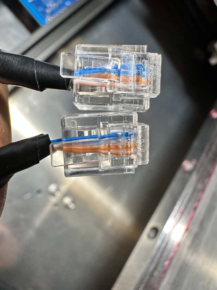
They are Straight through cable (Left to right ) and on both ends
- Blue, Blue-white, Orange, Orange-white
Technically , in this case , Blue-White and Orange wires are used by CAN Bus connection in Duet Boards
-
@developeralgo222 i don’t know if this matters that much for a short cable, but wires of the same colour, ie blue and white-with-blue-stripe, make up the twisted pair. These should be wired to the centre two pins that Duet use for CAN. The other pair goes on the pins outside these. You’re using one wire from each twisted pair.
Ian
-
@droftarts said in Duet 3HC Expansion looses Connection:
@developeralgo222 i don’t know if this matters that much for a short cable, but wires of the same colour, ie blue and white-with-blue-stripe, make up the twisted pair. These should be wired to the centre two pins that Duet use for CAN. The other pair goes on the pins outside these. You’re using one wire from each twisted pair.
Ian
Let me try it . i have tried almost everything Grounding, and everything in between that has been suggested but to no avail. Sometimes its usually the smallest thing that creates a nightmare.
-
@developeralgo222 said in Duet 3HC Expansion looses Connection:
@droftarts said in Duet 3HC Expansion looses Connection:
@developeralgo222 i don’t know if this matters that much for a short cable, but wires of the same colour, ie blue and white-with-blue-stripe, make up the twisted pair. These should be wired to the centre two pins that Duet use for CAN. The other pair goes on the pins outside these. You’re using one wire from each twisted pair.
Ian
Let me try it . i have tried almost everything Grounding, and everything in between that has been suggested but to no avail. Sometimes its usually the smallest thing that creates a nightmare.
Didn't make a difference at all .
I have tried every kind of Cable connection as per the requirement but there is no reliable sync of CAN connection. I don't believe i am the only one who is building a PnP or a 3D printer that is encountering this issue. i have worked with various kinds of connections and boards but have never encountered such an issue with CAN Bus.
Can't Sync 3HC boards no matter the cable. Have used the documentation to double check everything. Remake the cables and test them. Not sure if it might actually be a Duet 3 3HC Hardware issue that is causing this ?
-
@developeralgo222 said in Duet 3HC Expansion looses Connection:
Twisted pair cables terminated in RJ11 connectors are sold in some countries as "High Speed ADSL cables". One supplier of such cables is Kenable. Note, ADSL and telephone cables made with flat wire often cross the connections, making them unsuitable The price of kenable cables in US is so expensive while in UK they are extremely cheap. Can anyone point me to a link on Amazon or ebay for cable that works with Duet 3HC or 6XD CAN Bus without me cutting and remaking it, and is affordable
-
@developeralgo222 I'm sorry you're having so many problems with this. It really shouldn't be this difficult, and it has us foxed as well! Maybe the best option is to return to the last known working configuration, which was as a bench setup.
For cables in the USA on Amazon, these look like the correct ones: https://www.amazon.com/Kenable-Speed-Broadband-Modem-Cable/dp/B011SS7LYU
Ian
-
@droftarts said in Duet 3HC Expansion looses Connection:
@developeralgo222 I'm sorry you're having so many problems with this. It really shouldn't be this difficult, and it has us foxed as well! Maybe the best option is to return to the last known working configuration, which was as a bench setup.
For cables in the USA on Amazon, these look like the correct ones: https://www.amazon.com/Kenable-Speed-Broadband-Modem-Cable/dp/B011SS7LYU
Ian
I agree this should not be this difficult. I have checked and double checked a lot of things but i can't get the CAN Sync to work. I decided to close my eyes, curse as much as i can and then ordered those cables let's hope that those help. Will get them in a week.
-
@developeralgo222 said in Duet 3HC Expansion looses Connection:
@droftarts said in Duet 3HC Expansion looses Connection:
@developeralgo222 I'm sorry you're having so many problems with this. It really shouldn't be this difficult, and it has us foxed as well! Maybe the best option is to return to the last known working configuration, which was as a bench setup.
For cables in the USA on Amazon, these look like the correct ones: https://www.amazon.com/Kenable-Speed-Broadband-Modem-Cable/dp/B011SS7LYU
Ian
I agree this should not be this difficult. I have checked and double checked a lot of things but i can't get the CAN Sync to work. I decided to close my eyes, curse as much as i can and then ordered those cables let's hope that those help. Will get them in a week.
@dc42, @droftarts , What is the expected terminating resistors values at the end of the CAN Bus for Duet boards? Ideally , Each resistor should ideally be 120 ohm, for a 60 ohm difference between CANH and CANL. When i measure the resistance with Multimeter on the terminated 3HC Board i get a difference of 70.4 Ohms and for Unterminated CAN_H & CAN_L i get 126.6 Ohms ? are this the expected values ?
Was doing some research and to continue troubleshooting, came across some explanation
General CAN Bus wiring and troubleshooting concepts documentOther CAN Bus terminating resistor values can be used and calculated based on specific baudrates and bus lengths - but, as you increase the baudrate, the pickier it gets about correct termination, whereas on lower baudrates you can get away with missing terminating resistors, by chance Looking at the Duet Board / Schematic - i see Shield_GND terminal on the main board 6XD which i assume is for Ethernet Grounding.
Where is the CAN Grounding on Duet Boards ? since The CAN_GND of the CAN network should be connected to the functional earth potential (FE) at only one point i.e either on Main Board ( 6XD ) or on the Last 3HC on the Chain . Looking at the Kicad PCB design for 6XD , i see CAN_SHD_GND is that the same as CAN_GND in Duet 6XD design ?
-
@infiniteloop said in Duet 3HC Expansion looses Connection:
Is there anything I might be forgetting on this GND solution. I am trying to avoid creating GND loops
That’s complex. As a general rule, imagine a star topology, I.e. for each and every voltage, there should be a single point (or rail) from where to further route the power lines.
For your dual PSUs, you already have this central point: V+ (1 rail with 3 connectors on each PSU) is now interconnected as discussed above in this thread.
Now, if you connect GND (of the DC-output) to Earth, do it at a single point as well. Think of it as a common rail where all GND lines meet - kind of a ”local Earth”. Don’t take GND or V– from distant parts of the frame. Aside from the common rail, consider them as not being the same.
Voltage lines may be split or chained on their run, but may then never refer to another source of the same voltage again (that’s a loop). You often run into this trap with shielded lines: the shield carries GND (or, in some cases, V–), but if you supply GND from both ends, you might involuntarily establish a ground loop. The golden rule here is to always feed GND from the origin - leave it unconnected at the destination end.
The fact that most devices in your machine are controlled via V– complicates things. All switched V– lines from the DUETs may never have contact with the ”local Earth”, GND or any other V–.
Grounding the PnP machine is another topic: not all metal parts are always in touch with each other, there are potential isolators such as coatings, belts or lubricants in the way, some parts are clearly isolated by design (printed joints etc). Short cable bridges help in some cases, but for moving parts, you might need to route a dedicated GND line through your cable chain.
Considering USB ground loops, I recommend this article from the documentation: USB ground loops
@infiniteloop , @dc42 , @droftarts
Can you give detail on this ? Currently i have the 2 PSUs connected like this
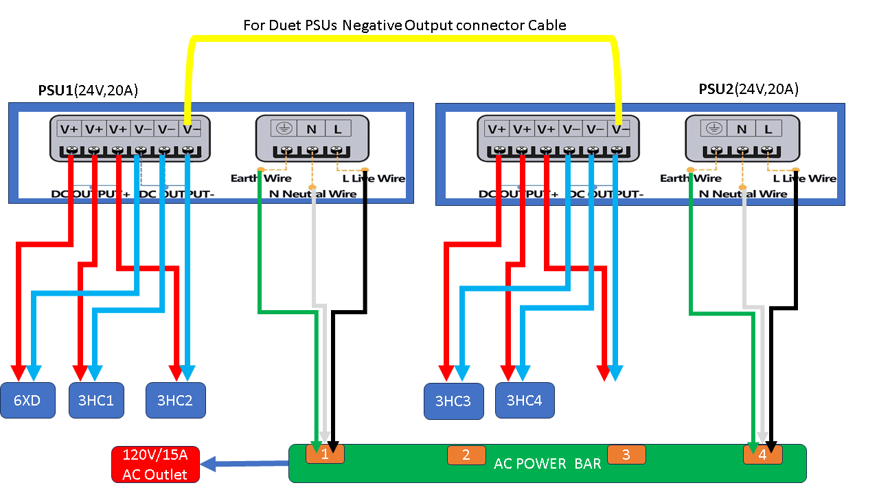
Do i need to connect anything differently here ?
-
@developeralgo222 said in Duet 3HC Expansion looses Connection:
Can you give detail on this ? Currently i have the 2 PSUs connected like this
I’d rather like to take the Monty Python turn: And now for something completely different …

Well, let’s see where we are:
- your wiring of the PSUs looks OK.
- the test setup for CAN with isolated boards works - am I right with this?
- if mounted on the PnP machine, only the CAN connection 6XD <-> 3HC „1“ works, all other connections fail - am I right with this?
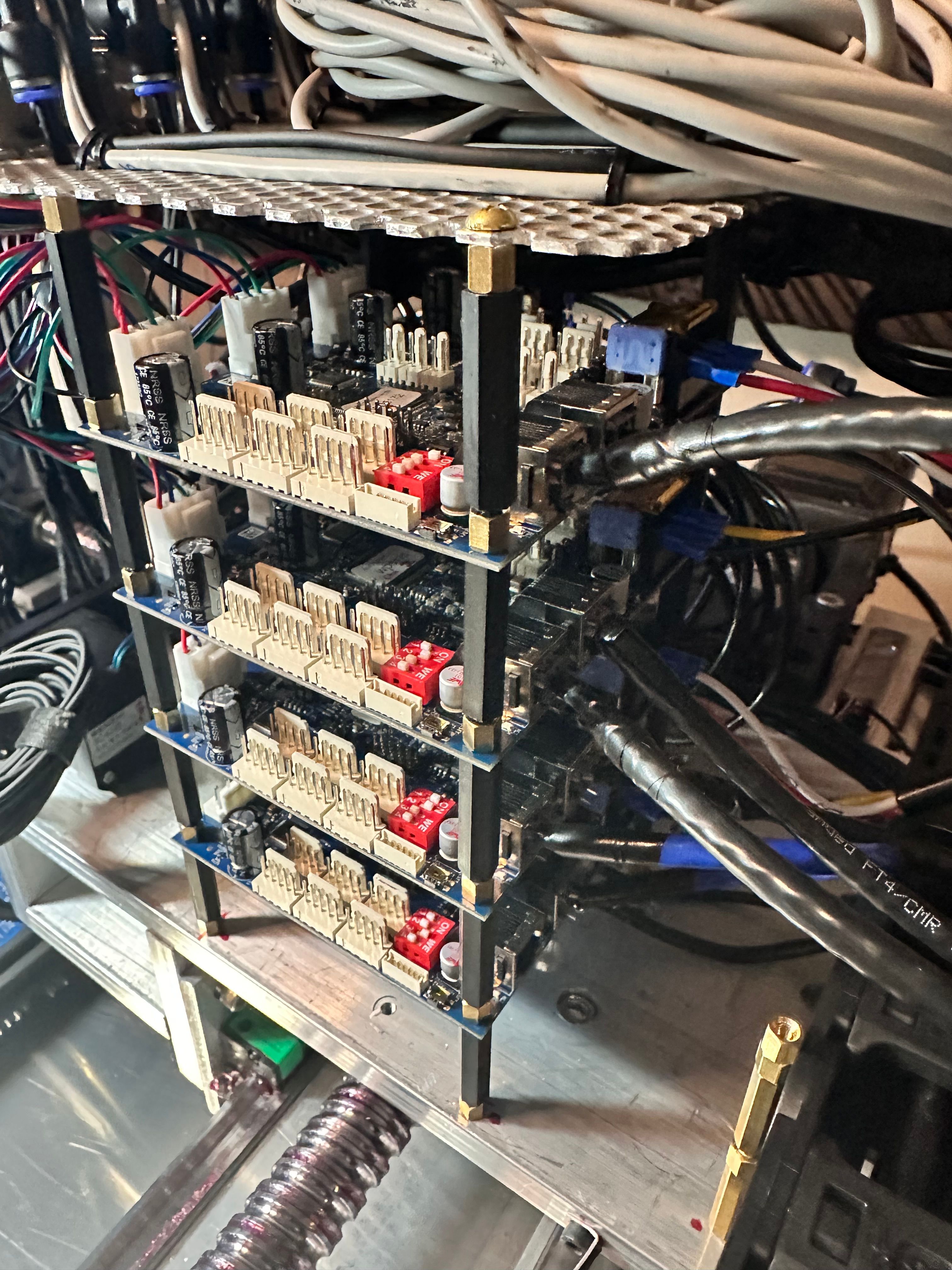
If this is the current state of affairs, I’d like you to run another test: As of the photo below, the boards are stacked with electrically conductive standoffs who are, in turn, attached to the frame of the PnP machine. Now, can you detach the whole stack from the machine - but keep the standoffs between the boards in place? I’d like to know whether CAN becomes dysfunctional due to the GND it gets from the PnP machine or due to the electrical interconnection of the boards via the standoffs alone.
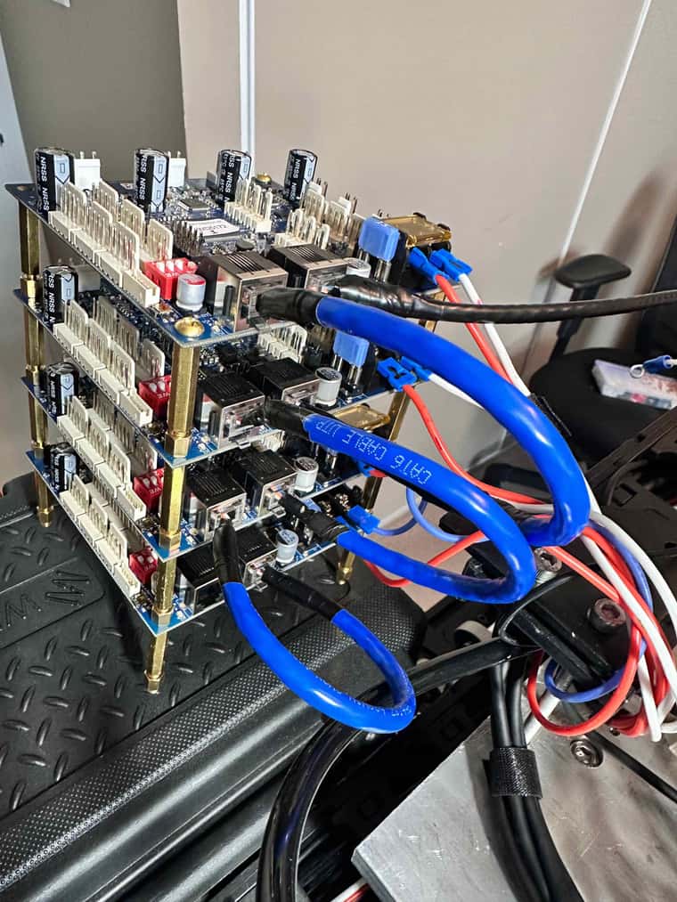
Please be assured that me, like @droftarts, am sorry for the problems you face. More so, I’m sincerely foxed by my inability to spot the root cause of the mystic CAN bus failure.
-
@infiniteloop The stack of boards in that image are standing on what looks like a plastic toolbox, not connected to the machine.
As far as I can tell, there is no copper in close proximity to the mounting holes, at least on the 3HC v1.0 I have in my hands. There's no exposed copper around the holes, no via through-plating, and it looks like the copper ground plane doesn't extend to the holes. So I'm pretty sure they are electrically isolated from each other.
@developeralgo222 Plugging the two power supplies in to the same power bar should be fine. While we don't advise the same thing to get around USB ground loops, putting the two earths as close to each other as possible should largely mitigate a ground loop, if the PSUs are similar. I don't know if there's something about the phasing between them causing a problem; I'm no electrical engineer!
However... to mitigate that, have you tried powering all boards from one PSU, at least for testing? One PSU should have plenty of current to power all the boards, so long as no demanding load is put on it. Boards usually draw around 200-300mA with no peripherals connected.
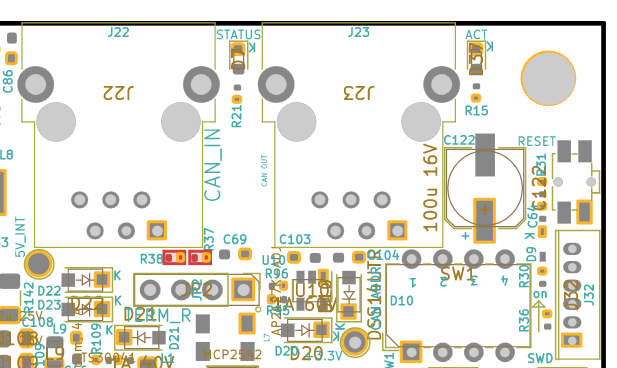
For the CAN question, I don't think termination resistors values need changing, because we (a) run at 1Mbit (ie not that fast) and (b) your CAN bus is short (less than five meters). The 70.4 Ohm reading on the terminated 3HC might be interesting; can you check the resistance in the same way on all the boards, and see if there has been damage to the R37 and R38? These are two tiny 59R resistors (I think they work in series to be around 120R) between the CAN RJ11 ports and the CAN termination jumpers. Highlighted red (from the ibom here) :
This is the circuit diagram:
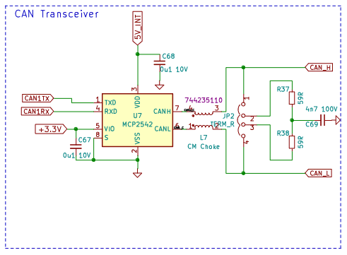
Though it may just be a measurement error.Ian
-
@droftarts said in Duet 3HC Expansion looses Connection:
@infiniteloop The stack of boards in that image are standing on what looks like a plastic toolbox, not connected to the machine.
As far as I can tell, there is no copper in close proximity to the mounting holes, at least on the 3HC v1.0 I have in my hands. There's no exposed copper around the holes, no via through-plating, and it looks like the copper ground plane doesn't extend to the holes. So I'm pretty sure they are electrically isolated from each other.
@developeralgo222 Plugging the two power supplies in to the same power bar should be fine. While we don't advise the same thing to get around USB ground loops, putting the two earths as close to each other as possible should largely mitigate a ground loop, if the PSUs are similar. I don't know if there's something about the phasing between them causing a problem; I'm no electrical engineer!
However... to mitigate that, have you tried powering all boards from one PSU, at least for testing? One PSU should have plenty of current to power all the boards, so long as no demanding load is put on it. Boards usually draw around 200-300mA with no peripherals connected.
For the CAN question, I don't think termination resistors values need changing, because we (a) run at 1Mbit (ie not that fast) and (b) your CAN bus is short (less than five meters). The 70.4 Ohm reading on the terminated 3HC might be interesting; can you check the resistance in the same way on all the boards, and see if there has been damage to the R37 and R38? These are two tiny 59R resistors (I think they work in series to be around 120R) between the CAN RJ11 ports and the CAN termination jumpers. Highlighted red (from the ibom here) :
This is the circuit diagram:
Though it may just be a measurement error.Ian
When i measure resistance across unterminated 3HC boards CAN_H & CAN_L i get 140 Ohms for Board 1, 2, 3 and then Board 4 is 70 Ohms which is correct because its terminated and that's the differential resistance. Early in my troubleshooting phase, i did try to power all from one PSU but that did not make a difference. i will try again for testing purpose .
-
@infiniteloop said in Duet 3HC Expansion looses Connection:
@developeralgo222 said in Duet 3HC Expansion looses Connection:
Can you give detail on this ? Currently i have the 2 PSUs connected like this
I’d rather like to take the Monty Python turn: And now for something completely different …
Well, let’s see where we are:
- your wiring of the PSUs looks OK.
- the test setup for CAN with isolated boards works - am I right with this?
- if mounted on the PnP machine, only the CAN connection 6XD <-> 3HC „1“ works, all other connections fail - am I right with this?
If this is the current state of affairs, I’d like you to run another test: As of the photo below, the boards are stacked with electrically conductive standoffs who are, in turn, attached to the frame of the PnP machine. Now, can you detach the whole stack from the machine - but keep the standoffs between the boards in place? I’d like to know whether CAN becomes dysfunctional due to the GND it gets from the PnP machine or due to the electrical interconnection of the boards via the standoffs alone.
Please be assured that me, like @droftarts, am sorry for the problems you face. More so, I’m sincerely foxed by my inability to spot the root cause of the mystic CAN bus failure.
i have updated the stands to Nylon standoff and completely isolated them using Nylon standoffs in between the boards. They no longer touch the frame or any metal attached to the frame.