Serial SCARA Configuration Issue
-
@o_lampe Thanks for taking a look, I read about that issue, but forgot about it while posting. Even if I use G90 then G1 X25 Y0 still looks "off", but G1 X25 Y25 does look reasonable. So looks like any axis that nears zero is a concern. Let me experiment some more.
-
@Imlbrown said in Serial SCARA Configuration Issue:
Since I have full 360 degree rotation, I set the angles in the M669 command to A-185:172 & B-174:186. This puts both arms exactly 180 degrees opposite of their homing point and half way thru their full travel angles.
This sentence confuses me.
A min and B min values are used as homing angles, so you should verify those angles first. Verify that G90 G1 H2 X0, X90 and X180 point to the right direction, same with the Y axis.I don't understand what you mean with 180 degrees and opposite. Neither -185-174 are -360 nor -185 and 172 add to a full 360 rotation. So I don't understand the sentences. Please explain.
-
@Imlbrown said in Serial SCARA Configuration Issue:
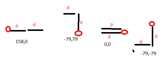
After homing, if I run G91 then G1 H2 X90 Y90 successive times the points (X, Y) are starting at home with 158, 0 then -79,79 then 0,0 then -79, -79. The Y values make complete sense, but the X values are an issue and I don't see where I went wrong.
This is exactly how you describe it:

Your G1 H2 commands are relative changes of arms, and the coordinates are absolute coordinates.Your 8.3,0 coordinates could be from a slight angle inexact measurement of the homing angles. You should measure the 0, 90, 180 angles exact and verify them.
0,0 has the added disadvantage that it has infinite solutions (every distal arm which is opposite from the proximal one, and any proximal angle is a solution, when both arms have the same length), so a movement from the position to a new position could have high velocity, depending on where the move before placed the arms.
When you move to an absolute position and are unsure why you don't get the expected result, you can check that the firmware calculated the correct position (i. e. it's not a rounding error e.g.) by calling M114 and checking the Count values, which are the value degrees * M92 value of this axis. (for linear axes it would be mm * M92 value). You can check the stored value for the homing points this way also.
-
Thanks for looking at this. Trying to explain the "180 degrees and opposite". I read in setup that once you hit your homing point, to set the A & B angles so that they place the are in the middle of the full movement of the arm. So after homing, I set A to be -185:175. since my full movement of X is 0 to 360, -180 is approx in the middle of the range of motion and the extra negative 5 degrees is just me trying to line of the X axis with a reference point I have on the machine.
@Imlbrown said in Serial SCARA Configuration Issue:
After homing, if I run G91 then G1 H2 X90 Y90 successive times the points (X, Y) are starting at home with 158, 0 then -79,79 then 0,0 then -79, -79. The Y values make complete sense, but the X values are an issue and I don't see where I went wrong.
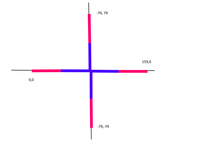
You drew what I would expect for the coordinates, but my image is where the arms actually were with the coordinates reported. Note: the 159,0 coordinate should have been 158, 0.

They don't make sense to me given the location of the arms. I have to ask, if I made a relative move, why wouldn't the coordinates reflect the actual position of the tool (end of the distral arm)? This is my first venture beyond Cartesian 3d printers, but I thought if you performed a relative move the x,y coordinates would still be accurate, can you explain the diff between relative angle moves and absolute coordinates in a scara configuration?I just realized, the command G1 H2 X90 Y90, was not rotating the Y (distral) arm, why does the diagram you drew not reflect what actually happened.
-
@Imlbrown said in Serial SCARA Configuration Issue:
So after homing, I set A to be -185:175
the config file is processed one line after another, so the M669 A and B settings are evaluated at the beginning, so your homing files use this setting, i. e. the G1 H1 will set the homing angle to -185. You can verify it: when homed and the arm is at the endstop, make a M114 to check the Count value.
You're right, the distal arm doesn't behave as expected, it should rotate in respect to the proximal arm. I'll try to find the reason in your config => maybe hiding Z is the reason:
As fast experiment:
In a different kinematics (parallel Scara) there are problems if there is no Z axis, this may be here the same. In the kinematics, often XYZ are handled together in multiple methods, so every axis must exist. Instead of hiding, define Z to use one movement chip on the board and just ignore Z after that. But I would set arbitrary values for M350, M92, M566, M201, M203, M906 for Z as well.
Then hide the M584 line, add a M569 setting for Z and try the G1 H2 moves again.
-
@Imlbrown there is another point: the line M92 Z0 in your config should be removed: Z is not defined so it makes no sense, and if you're unlucky the firmware divides by 0 somewhere (because steps per degree or mm may be used in calculations), stopping processing of code.
-
Thanks for the Z axis tip, I will test this out tonight and report back.
-
The M92 Z0 was a mistake, I meant G92 Z0 (set Z axis to zero). I was able to perform the test again with multiple configs; z-axis homed to 0 and another pass with z=1, with no z-axis at all, but still set to zero, all configs yielded the same results. After initial homing my points were 159.2, 0. I then ran G91 then G1 H2 X90 Y90 three successive times. Each time, only the proximal arm rotated and the distral kept inline with with the proximal arm, just as my original image with the blue and red arms. The subsequent x,y coordinates changed slightly, but were similar and in the same quadrants. In order, after homing, the points were (-70.7, 70.7), (0, 15.8) and (-86.5, -86.5) .
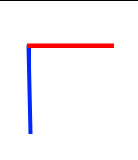
I realized the G1 H2 X90 Y90 command is working correctly. Since my cross talk is 0, if I only ran X90 it would look like this.

After the command G1 X90 Y90, both arms would be pointing straight up as in my previous red/blue diagram.
I think that mystery is solved, but the resulting coordinates for x and y still don't make sense for me.
Can you elaborate on your comments on absolute coordinates from a previous reply and how they relate to relative angle moves? Once setup correctly, if I issue the command absolute G1 X50 Y50, the tool head should go to the x,y coordinate specified, yes? And if I issue absolute G1 H2 X0 Y0 then then both arms should go to the absolute zero angles, yes?
Also, I see varying settings from diff posts trying to configure the same. Does it matter which direction the proximal and distral arms rotate (clockwise or counter clockwise) given a relative positive angle? If so, which way should each arm rotate given a positive relative angle command like G91 then G1 H2 X90?
config.g
M929 P"debug.log" S1; turn on logging to web interface

M552 S1                                           ; enable networking/wifi

M84 600 ;idle timeout

M575 P1 S1 B57600  ;Enable PanelDue

; Network
M550 P"SCARA Sandbot" ; Set machine name

M586 P0 S1  ; Enable HTTP
M586 P1 S0  ; Disable FTP
M586 P2 S1  ; Enable Telnet

M584 X0 R1 Y1 R1;  P2 ; drive 1 (x) rotation, drive 2 (y) rotational, P2 hides Z-axis


M569 P0 S0 D2  ; Drive 0 (X)
M569 P1 S0 D2  ; Drive 1 (Y)


M208 X-160:160 Y-160:160 Z0:0  ; set machine limits
M350 X16 Y16  ; Configure micro-stepping with interpolation

M92 X26.666666667 Y26.666666667     ; Steps per degree. (200 steps/rev * 16 microsteps * 60t/20t) / 360 degree
M566 X25 Y25  ; max instantaneous change in accel/jerk
M201 X250 Y250 ; acceleration
M203 X8000 Y8000 ; max speed (mm/min)
M906 X400 Y400 I20 ; motor current in mA

;Set SCARA
M669 K4 P79 D79 A-185:175 B-178.75:181.25 S1000 T0.01 R0 C0:0:0; X100 Y-50; X112 Y-66

;Endstops
M574 X1 S1 P"!xstop"   ; X min active low endstop switch
M574 Y1 S1 P"!ystop"   ; Y min active low endstop switch
Thanks!
-
@Imlbrown I once made a post on coordinates https://forum.duet3d.com/topic/17222/duet3d-3-custom-delta-printer-inconsistant-motor-problems/14 explaining the different meanings of XYZ, depending on the G-Code command. This may explain some of my statements. So it would be more clear to name proximal arm stepper A and distal one stepper B, but this is not common.
If you have little coordinate errors in the resulting position of 0,0, I expect it to be either
- homing angles are not exactly as defined
- some arm bending in Z direction or play in the hinges
- arm lengths different than specified
- 5% tolerance errors of the steppers. But this results in about 0.3 mm only for your arm lengths.
Your question, whether it matters which direction: it depends on the kinematics whether they are handled correctly. Sometimes rotating big angles is not handled correctly or such a rotation uses a direction which you don't expect (e.g. -350 instead of the expected 10 rotation). Rotating 360 more than one time can result in problems because the wires/filament are winded up, so the kinematics should store the number of full rotations (and maybe rotate back in pauses, i.e. between movements) and it takes longer, resulting in timing problems, but to my knowledge this is not implemented. Your slicer must take care to generate correct G-Code.
Your question which direction each arm should take: the convention for angles is that if you look onto the axis from the arrow side, counterclockwise is positive and clockwise is negative. So it's beneficial to make an image in which direction your axes are pointing. The direction of axes and the coordinate system must match. (right hand coordinate system Xright Yback Ztop).
And if I issue absolute G1 H2 X0 Y0 then then both arms should go to the absolute zero angles, yes?
Yes
Hope I solved some of your questions.
-
@Imlbrown depending on your controller hardware, M669 S1000 may be too high. A hint whether it's too high is to make some complex moves (e.g.. G2, G3 arcs *) ), then call M122 and look whether hiccups are reported, which are lost steps.
*) but long G1 moves are also complex with your kinematics, because rotational actuators behave nonlinear