SKR 2 + RRF36
-
@justGuner That looks ok to me. But your CAN-FD module is not being detected. Things you could try....
- It looks like the dfd module may expect an extra ground pin (pin 8 on the dfd connector, basically the pin at the opposite end to your current VCC connection. I'm not sure if it is needed, but it would normally be connected. Make sure you check the schematic before adding that wire though.
- You could try lowering the SPI frequency used to talk to the DFD. try adding:
can.spiFrequencyHz = 10000000To your board.txt file. If that is still not working try:
can.spiFrequencyHz = 5000000Other than that I'm out of ideas other than checking the actual wiring and that the pins actually go where they look like they are going.
-
@gloomyandy The other thing you could try is to connect the power for the DFD directly to the 12/24V supply. The SKR2 has a rather wacky power circuit for the drivers that may mean power for the DFD is being delayed, and it could be that the detection code has run before the DFD has settled down.
-
@gloomyandy I have connected the dfd directly to the 24v supply, and immediately began to experience mainboard reset loops upon power-up. I've removed the gnd wire, and now everything powers up as before, but there is stil no can comunication (I did try the above mentioned frequencies).
I am reaching the point where it might not be worth it to try and make this work and just buy the EFD and wait 2 weeks.
-
To add salt to the injury, I thought that maybe I needed to connect the additional int0 and int1 pins. That didn't deliver the expected outcome... (I fried the DFD, hopefully nothing else)
And so, I will post an update on the situation after receiving the EFD in I'm guessing about 2 weeks.
Finally, a little suggestion: you might want to add the reason for why it is recommended to go with the EFD on the teamgloomy website. Not just for the skr2, but for other boards as well.
-
@justGuner A quick follow up. I've just tested a EFD with an SKR2 and RRF 3.5, seems to be working fine. Jay has also updated the documentation to say that only the EFD will work on those boards for which this is the case.
-
After recieving the EFD, I can confirm that I have a connection between the skr and the toolboard. However, upon boot, I receive "invalid Z probe index" errors, and an incompatible software warning.
curent software versions:
I also tried with rc.3; same outcome
Here is the updated config :
; Configuration file for BTT SKR 2 (firmware version 3) ; executed by the firmware on start-up ; ; generated by RepRapFirmware Configuration Tool v3.4.0-LPC-STM32+7 on Sun Aug 20 2023 12:46:47 GMT+0300 (Eastern European Summer Time) ; General preferences G4 S2 ; wait 2 seconds G90 ; send absolute coordinates... M83 ; ...but relative extruder moves M550 P"My Printer" ; set printer name M669 K1 ; select CoreXY mode ; Network M552 S1 ; enable network M586 P0 S1 ; enable HTTP M586 P1 S0 ; disable FTP M586 P2 S0 ; disable Telnet ; Drives M569 P0 S1 ; physical drive 0 goes forwards using default driver timings M569 P1 S1 ; physical drive 1 goes forwards using default driver timings M569 P2 S0 ; physical drive 2 goes backwards using default driver timings M569 P3 S0 ; physical drive 3 goes backwards using default driver timings M569 P124.0 S1 ; physical drive 124.4 goes forwards using default driver timings M584 X0 Y1 Z2:3 E124.0 ; set drive mapping M350 Z256 E256 I0 ; configure microstepping without interpolation M350 X16 Y16 I1 ; configure microstepping with interpolation M92 X80.00 Y80.00 Z6400.00 E415 ; set steps per mm M566 X900.00 Y900.00 Z60.00 E1200.00 ; set maximum instantaneous speed changes (mm/min) M203 X30000.00 Y30000.00 Z1000.00 E3000.00 ; set maximum speeds (mm/min) M201 X10000.00 Y10000.00 Z300.00 E1000.00 ; set accelerations (mm/s^2) M906 X800 Y800 Z1200 E800 I30 ; set motor currents (mA) and motor idle factor in per cent M84 S30 ; Set idle timeout ; Axis Limits M208 X0 Y0 Z0 S1 ; set axis minima M208 X260 Y260 Z350 S0 ; set axis maxima ; Endstops M574 X2 S1 P"xstop" ; configure switch-type (e.g. microswitch) endstop for high end on X via pin xstop M574 Y2 S1 P"ystop" ; configure switch-type (e.g. microswitch) endstop for high end on Y via pin ystop M574 Z1 S2 ; configure Z-probe endstop for low end on Z ; Z-Probe M950 S0 C"124.io0.out" ; create servo pin 0 for BLTouch M558 P9 H6 F250:30 T8000 C"124.io0.in" ; set Z probe type to bltouch and the dive height + speeds G31 P500 X-22.345 Y-6.941 Z2.436523 ; set Z probe trigger value, offset and trigger height M557 X15:215 Y15:195 S20 ; define mesh grid ; Heaters M308 S0 P"bedtemp" Y"thermistor" T100000 B4092 ; configure sensor 0 as thermistor on pin bedtemp M950 H0 C"bed" T0 ; create bed heater output on bed and map it to sensor 0 M307 H0 B0 S1.00 ; disable bang-bang mode for the bed heater and set PWM limit M140 H0 ; map heated bed to heater 0 M307 H0 R0.320 K0.414:0.000 D1.01 E1.35 S1.00 B0 V24.6 ; set PID values for heated bed M143 H0 S130 ; set temperature limit for heater 0 to 120C M308 S1 P"124.temp0" Y"thermistor" T100000 B4092 ; configure sensor 1 as thermistor on pin e0temp M950 H1 C"124.out0" T1 ; create nozzle heater output on e0heat and map it to sensor 1 M307 H1 B0 S1.00 ; disable bang-bang mode for heater and set PWM limit M143 H1 S300 ; set temperature limit for heater 1 to 300C M307 H1 R3.201 K0.662:0.000 D9.07 E1.35 S1.00 B0 V24.0 ; set PID values for heater 1 ; Fans M950 F0 C"124.out1" Q250 ; create fan 0 on pin fan0 and set its frequency M106 P0 S0 H-1 ; set fan 0 value. Thermostatic control is turned off M950 F1 C"124.out2" Q500 ; create fan 1 on pin fan1 and set its frequency M106 P1 S0 H1 T100 ; set fan 1 value. Thermostatic control is turned on ;M308 S2 P"e1temp" Y"thermistor" T100000 B4092 A"Bed mosfet" ; Tools M563 P0 D0 H1 F0 ; define tool 0 G10 P0 X0 Y0 Z0 ; set tool 0 axis offsets G10 P0 R0 S0 ; set initial tool 0 active and standby temperatures to 0C ; Custom settings are not defined ; Miscellaneous T0 ; select first tool ;M955 P0 C"PE_10+PE_9" I20 M572 D0 S0.085 M912 P0 S-8.9 ;M593 P"zvddd" F44.8 ; use ZVDDD input shaping to cancel ringing at 46.1Hz M308 S2 Y"drivers" A"DRIVERS" ; configure sensor 2 as temperature warning and overheat flags on the TMC2660 on Duet M308 S3 Y"mcu-temp" A"MCU" ; configure sensor 3 as on-chip MCU temperature sensor M950 F2 C"fan2" Q20000 ; create fan 2 on pin fan2 and set its frequency M106 P2 H2:3 L0.15 X0.65 B0.3 T40 ; set fan 2 value -
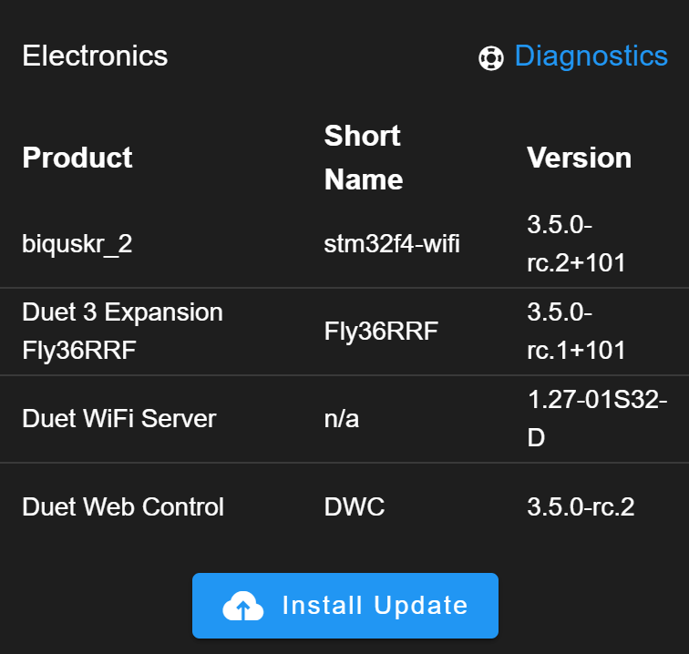
@justGuner You need to use the same version for all of the components, your screen shot shows a mixture of rc.1 and rc.2. If you think you have the correct versions installed run M122 and M122 B124 and post the output here.
M574 Z1 S2 ; configure Z-probe endstop for low end on Z
You also have the above in your config. See the following notes for option S2:
The S2 option of M574 is intended for use only when axes other than Z are using the Z probe for homing. The only printers known that do this using Duet electronics are the RepRapPro Ormerod, Huxley Duo, and Mendel Tricolour machines. When using the Z probe to home Z, M574 Z has no bearing on the probe setup or usage. A Z probe and a Z endstop can both be configured at the same time. G30 calling the probe setup with M558, and G1 H1 Z moves calling the endstop configured with M574 Z.
That may be generating the probe error as at that point in the config, you have not defined a probe. Either way you almost certainly do not need that setting and should probably delete it.
-
@gloomyandy I updated every component to rc.3 and now everything works as it should. Originally I thought that the latest version for the rrf36 was rc.1; apparently I just wasn't patient enough for it to update over usb and it would boot up with the old one.
Thanks for the help.
-
@justGuner Once a version of RRF is installed on the toolboard you should be able to update via CAN-FD no need to do it via USB.
-
@gloomyandy good to know