Duet3D Logo Duet3D
    • Tags
    • Documentation
    • Order
    • Register
    • Login

    how to setup a hotend for directly printing metal and ceramic.

    Scheduled Pinned Locked Moved Unsolved
    Hardware dev
    6
    59
    2.2k
    Loading More Posts
    • Oldest to Newest
    • Newest to Oldest
    • Most Votes
    Reply
    • Reply as topic
    Log in to reply
    This topic has been deleted. Only users with topic management privileges can see it.
    • lynnmtundefined
      lynnmt @dc42
      last edited by

      @dc42
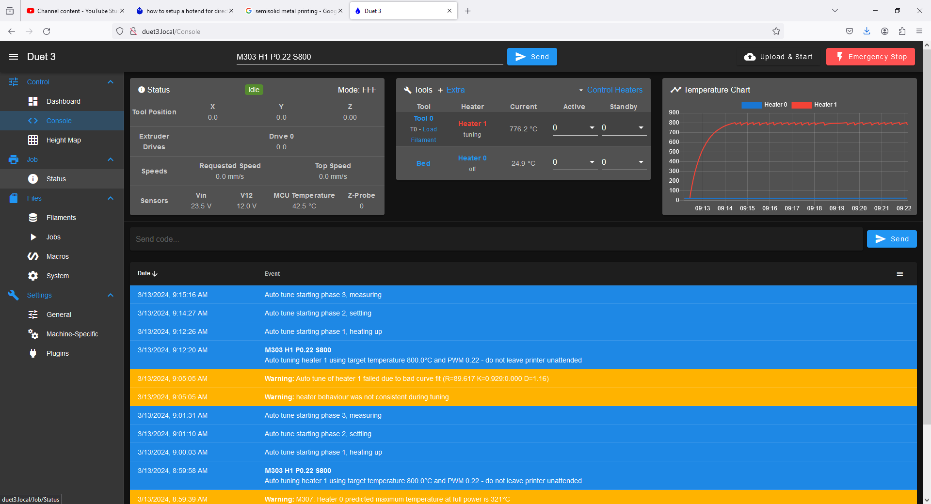
      "Auto tune of heater 1 failed due to bad curve fit (R=89.617 K=0.929:0.000 D=1.16)"

      dc42undefined 1 Reply Last reply Reply Quote 0
      • dc42undefined
        dc42 administrators @lynnmt
        last edited by dc42

        @lynnmt thanks. Can you post a screenshot of the temperature while tuning?

        PS - the maximum value of Y supported is currently 20. So I suggest you try Y20 in the M303 command.

        Duet WiFi hardware designer and firmware engineer
        Please do not ask me for Duet support via PM or email, use the forum
        http://www.escher3d.com, https://miscsolutions.wordpress.com

        lynnmtundefined 1 Reply Last reply Reply Quote 0
        • lynnmtundefined
          lynnmt @dc42
          last edited by lynnmt

          @dc42 steady800Cautotune.PNG

          some images....the first is the requested screen capture.

          this last tune I screep caped had this warning:
          "Auto tune of heater 1 failed due to bad curve fit (R=61.202 K=0.807:0.000 D=1.59)"

          dc42undefined 1 Reply Last reply Reply Quote 1
          • dc42undefined
            dc42 administrators @lynnmt
            last edited by dc42

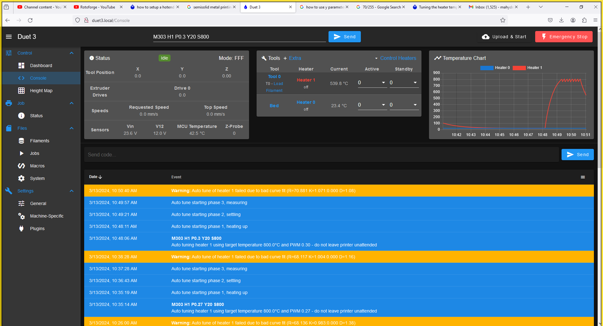
            @lynnmt thanks. Please try tuning again with a higher PWM (maybe 0.3 or 0.35) and Y20. At the current PWM the heater is barely capable of reaching 800C.

            Duet WiFi hardware designer and firmware engineer
            Please do not ask me for Duet support via PM or email, use the forum
            http://www.escher3d.com, https://miscsolutions.wordpress.com

            lynnmtundefined 3 Replies Last reply Reply Quote 0
            • lynnmtundefined
              lynnmt @dc42
              last edited by

              @dc42 800cautotunebadcurvefit.PNG

              as requested.
              seems to provide the same error with model parameters:
              "Auto tune of heater 1 failed due to bad curve fit (R=70.881 K=1.071:0.000 D=1.08)"

              what does this mean?

              dc42undefined 2 Replies Last reply Reply Quote 0
              • lynnmtundefined
                lynnmt @dc42
                last edited by

                @dc42
                I would also mention that it is not the heater it is the thermocouple whose temperature is below the setpoint at the output power due to all the insulation around the Thermocouple.

                the heater itself is glowing white hot.

                e591165d-7198-448c-b205-80c16737f063-image.png

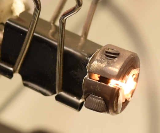
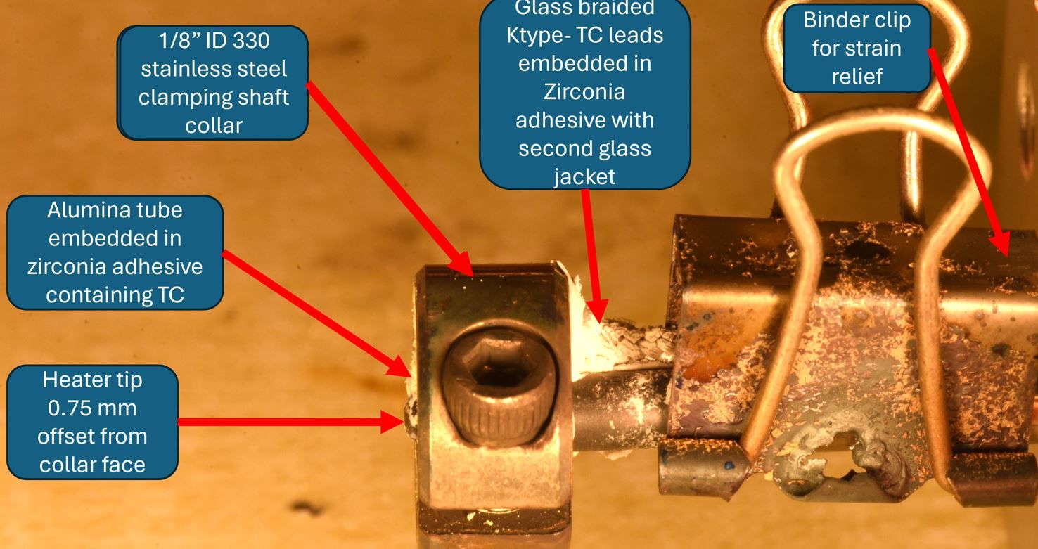
                here is a picture of the setup. the thermocouple is inside a 0.05" OD aluminum oxide sheath inside the stainless steel ring, pasted on with zirconia paste as close as possible to the heater.

                1 Reply Last reply Reply Quote 0
                • lynnmtundefined
                  lynnmt @dc42
                  last edited by

                  @dc42
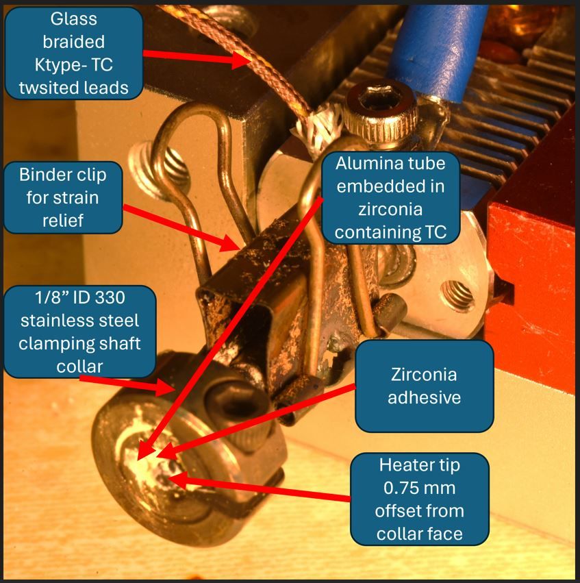
                  if it helps here are some more hardware shots...
                  tcmountinghardwareshotfront.JPG tcmountinghardwareshot.JPG

                  lynnmtundefined 1 Reply Last reply Reply Quote 0
                  • dc42undefined
                    dc42 administrators @lynnmt
                    last edited by

                    @lynnmt that looks like a good tuning cycle. I'll look at why the resulting parameters are rejected and see if it makes sense to widen the limits. Thanks for the photos.

                    Duet WiFi hardware designer and firmware engineer
                    Please do not ask me for Duet support via PM or email, use the forum
                    http://www.escher3d.com, https://miscsolutions.wordpress.com

                    lynnmtundefined 1 Reply Last reply Reply Quote 0
                    • lynnmtundefined
                      lynnmt @dc42
                      last edited by lynnmt

                      @dc42 I am working on making the sensor response even faster.
                      so I would expect the limits to need to be substantially wider even than those determined by the autotune.
                      in practice, making up for sensor delay in a system like this is going to be a huge problem. 😕

                      Thanks for taking a look!
                      I will be in touch here and on the discord!

                      lynnmtundefined 1 Reply Last reply Reply Quote 0
                      • dc42undefined
                        dc42 administrators @lynnmt
                        last edited by

                        @lynnmt said in how to setup a hotend for directly printing metal and ceramic.:

                        R=70.881 K=1.071:0.000 D=1.08

                        This command works for me:

                        M307 H0 R70.881 K1.071:0.000 D1.08

                        So I think that in RRF 3.5.x the limits have already been extended sufficiently. Please try upgrading to the RRF 3.5.0 build. As you are using an attached SBC you will need to upgrade to 3.5.0-rc.3. After that you may optionally upgrade to the latest RRF 3.5 firmware binary from https://www.dropbox.com/scl/fo/ljnewqssbl9bdo9vex37f/h?rlkey=m11nef0mvuc9pc8wri7rabf1b&dl=0.

                        Duet WiFi hardware designer and firmware engineer
                        Please do not ask me for Duet support via PM or email, use the forum
                        http://www.escher3d.com, https://miscsolutions.wordpress.com

                        lynnmtundefined 2 Replies Last reply Reply Quote 0
                        • lynnmtundefined
                          lynnmt @lynnmt
                          last edited by lynnmt

                          @lynnmt Ah! I forgot to mention a important detail!

                          the glowplug heater is PTC!

                          1 Reply Last reply Reply Quote 0
                          • lynnmtundefined
                            lynnmt @dc42
                            last edited by

                            @dc42
                            excellent. Thanks for running the test.
                            I will try the upgraded firmware.
                            A further question,
                            is there some way to know what these heater limits are and to make them user adjustable without needing to compile firmware?

                            all the best,
                            Michael Lynn

                            1 Reply Last reply Reply Quote 0
                            • lynnmtundefined
                              lynnmt @lynnmt
                              last edited by lynnmt

                              @lynnmt
                              is this an unstable package release?

                              also,
                              will the instructions here be sufficient for making this firmware update or are there other sources to consider?

                              https://docs.duet3d.com/User_manual/Machine_configuration/DSF_RPi#software-installation

                              when I run the commands suggested for upgrading to unstable releases, here:
                              sudo rm -f /etc/apt/sources.list.d/duet3d.list
                              sudo bash -c "echo 'deb https://pkg.duet3d.com/ unstable armv7' > /etc/apt/sources.list.d/duet3d-unstable.list"

                              my command prompt on SBC returns

                              bash - "permision denied"

                              1 Reply Last reply Reply Quote 0
                              • lynnmtundefined
                                lynnmt @dc42
                                last edited by

                                @dc42
                                I have successfully upgraded to RRF 3.5.0-rc.3.
                                Autotuning of my heater still fails with the warning

                                running M303 H1 Y20 P0.27 S750 returns:

                                "Autotune failed due to bad curve fit (R=53.131 K=0.801:0.000 D=1.25)

                                If i then take the provided model parameters, and plug them into M307 as:
                                M307 H1 R53.131 K0.801 D1.25
                                this command returns

                                Error M307 : Bad model parameters.

                                The autotune makes a very nice curve, see picture here:
                                66bc7655-cc32-4f60-a35d-120b175ef507-image.png

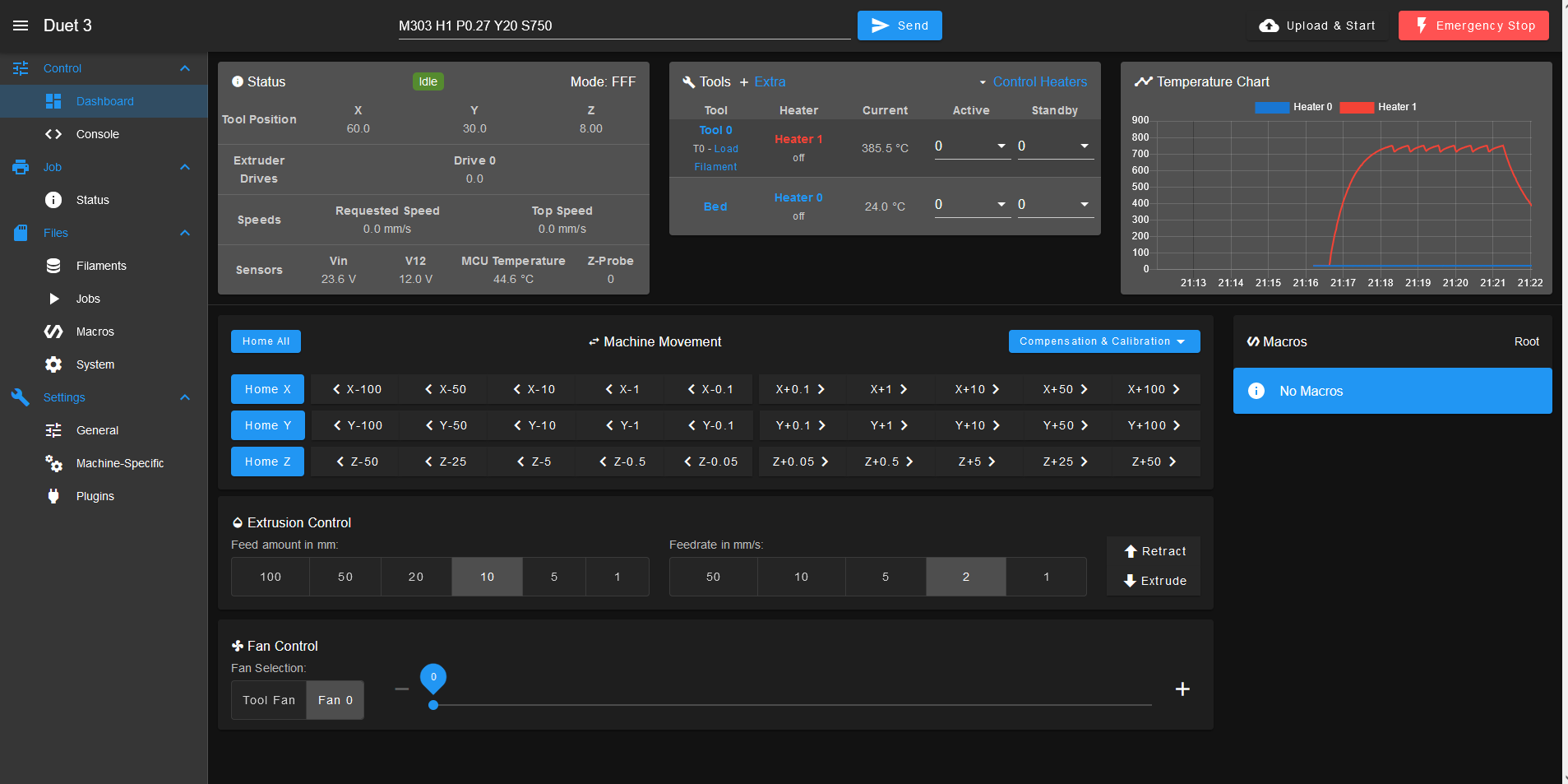
                                Not sure what to make of this.

                                dc42undefined 1 Reply Last reply Reply Quote 0
                                • dc42undefined
                                  dc42 administrators @lynnmt
                                  last edited by dc42

                                  @lynnmt do you have a temperature limit set for that heater? Use M143 H1 to check. If so then it may be set too low. If the heater has been assigned to a tool then it will have a default temperature limit. I found that I needed to increase the temperature limit to 1750C (M143 H1 S1750) for those parameters to be accepted.

                                  Please post your config.g file.

                                  Duet WiFi hardware designer and firmware engineer
                                  Please do not ask me for Duet support via PM or email, use the forum
                                  http://www.escher3d.com, https://miscsolutions.wordpress.com

                                  lynnmtundefined 1 Reply Last reply Reply Quote 0
                                  • lynnmtundefined
                                    lynnmt @dc42
                                    last edited by

                                    @dc42

                                    config.g

                                    ; Configuration file for Duet 3 MB 6HC (firmware version 3.3)
                                    ; executed by the firmware on start-up
                                    ;
                                    ; generated by RepRapFirmware Configuration Tool v3.4.1 on Fri Feb 23 2024 23:32:11 GMT-0600 (Central Standard Time)
                                    
                                    ; General preferences
                                    G90                                          ; send absolute coordinates...
                                    M83                                          ; ...but relative extruder moves
                                    M550 P"Duet 3"                               ; set printer name
                                    M918 P1 E4 F2000000                          ; configure direct-connect display
                                    
                                    ; Drives
                                    M569 P0.0 S0                                 ; physical drive 0.0 goes backwards
                                    M569 P0.1 S1                                 ; physical drive 0.1 goes forwards
                                    M569 P0.2 S1                                 ; physical drive 0.2 goes forwards
                                    M569 P0.3 S0                                 ; physical drive 0.3 goes backwards
                                    M584 X0.0 Y0.1 Z0.2 E0.3                     ; set drive mapping
                                    M350 X16 Y16 Z16 E16 I1                      ; configure microstepping with interpolation
                                    M92 X80.00 Y80.00 Z400.00 E93.00             ; set steps per mm
                                    M566 X1200.00 Y1200.00 Z24.00 E300.00        ; set maximum instantaneous speed changes (mm/min)
                                    M203 X9000.00 Y9000.00 Z180.00 E6000.00      ; set maximum speeds (mm/min)
                                    M201 X500.00 Y500.00 Z100.00 E5000.00        ; set accelerations (mm/s^2)
                                    M906 X800 Y800 Z800 E1000 I50                ; set motor currents (mA) and motor idle factor in per cent
                                    M84 S30                                      ; Set idle timeout
                                    
                                    ; Axis Limits
                                    M208 X0 Y0 Z0 S1                             ; set axis minima
                                    M208 X235 Y235 Z250 S0                       ; set axis maxima
                                    
                                    ; Endstops
                                    M574 X1 S1 P"io1.in"                         ; configure switch-type (e.g. microswitch) endstop for low end on X via pin io1.in
                                    M574 Y1 S1 P"io2.in"                         ; configure switch-type (e.g. microswitch) endstop for low end on Y via pin io2.in
                                    M574 Z1 S2                                   ; configure Z-probe endstop for low end on Z
                                    
                                    ; Z-Probe
                                    M950 S0 C"io5.out"                           ; create servo pin 0 for BLTouch
                                    M558 P9 C"io5.in" H5 F120 T6000              ; set Z probe type to bltouch and the dive height + speeds
                                    G31 P500 X0 Y0 Z3                            ; set Z probe trigger value, offset and trigger height
                                    M557 X60:215 Y30:195 S20                     ; define mesh grid
                                    
                                    ; Heaters
                                    M308 S0 P"temp0" Y"thermistor" T100000 B4092 ; configure sensor 0 as thermistor on pin temp0
                                    M950 H0 C"out0" T0                           ; create bed heater output on out0 and map it to sensor 0
                                    M307 H0 B1 S1.00                             ; enable bang-bang mode for the bed heater and set PWM limit
                                    M140 H0                                      ; map heated bed to heater 0
                                    M143 H0 S150                                 ; set temperature limit for heater 0 to 150C
                                    M308 S1 P"spi.cs0" Y"thermocouple-max31856"  ; configure sensor 1 as thermocouple via CS pin spi.cs1
                                    M950 H1 C"out1" T1                           ; create nozzle heater output on out1 and map it to sensor 1
                                    M307 H1 B0 S0.10                             ; disable bang-bang mode for heater  and set PWM limit
                                    M143 H1 S900                                ; set temperature limit for heater 1 to 900C
                                    
                                    ; Fans
                                    M950 F0 C"out7" Q500                         ; create fan 0 on pin out7 and set its frequency
                                    M106 P0 S0 H-1                               ; set fan 0 value. Thermostatic control is turned off
                                    
                                    ; Tools
                                    M563 P0 D0 H1 F0                             ; define tool 0
                                    G10 P0 X0 Y0 Z0                              ; set tool 0 axis offsets
                                    G10 P0 R0 S0                                 ; set initial tool 0 active and standby temperatures to 0C
                                    
                                    ; Custom settings are not defined
                                    
                                    ; Miscellaneous
                                    M501                                         ; load saved parameters from non-volatile memory
                                    T0                                           ; select first tool
                                    

                                    I have set the temperature limit to 900 C.
                                    why would there be a minimum limit for the model parameters to be accepted?
                                    my heater cannot be allowed to operate above about 1300 C in air for an extended period, or its resistance will drift.
                                    I set a lower limit, because the thermocouple has a large offset temperature and I dont know it exactly. so I set a conservative limit, as I wanted to avoid destroying my heater.

                                    soare0undefined 1 Reply Last reply Reply Quote 0
                                    • soare0undefined
                                      soare0 @lynnmt
                                      last edited by soare0

                                      @lynnmt I think it is only for the model to work. Normally, it should be a real ”limit” here, and for the heaters wich I not did autotune (or failed, probably because of the same problem as yours now, and for wich I set the model parameters manually), I get some warnings like: ”your temperature may reach XXX degrees”, but this did not happened... yet.

                                      M143 H4 S100                                        ; set temperature limit for heater 1 to 100C
                                      

                                      And the model:

                                      M307 H4 R0.217 K0.124:0.000 D19.84 E1.35 S1.00 B1
                                      

                                      So the software warns me at start-up that based on my M307, and ... do not know what else, the heater will reach 176C. I could not care less, as it works, just an annoying message more.

                                      1 Reply Last reply Reply Quote 0
                                      • lynnmtundefined
                                        lynnmt
                                        last edited by lynnmt

                                        So after taking @dc42 suggestion and raising the temperature limit to 1750C,
                                        the Autotune (at 700 C target temperature and 0.27 pwm limit with Y20) worked and returned parameters:

                                        Heater 1: heating rate 44.460, cooling rate 0.824, dead time 1.70, max PWM 0.27, mode PID, calibrated at 23.6V
                                        Predicted max temperature rise 1918°C
                                        PID parameters: heating P2.4 I0.233 D2.8, steady P2.4 I0.499 D2.8

                                        This seems to be reliable enough given my janky current setup to transfer to the working printhead.

                                        We also characterized the offset temperature from the glowplug tip to the thermocouple y measuring the tip temperature with an identical type K thermocouple.

                                        here is the result
                                        38f93781-ccbd-4f0f-889b-89bd0fe312a5-image.png

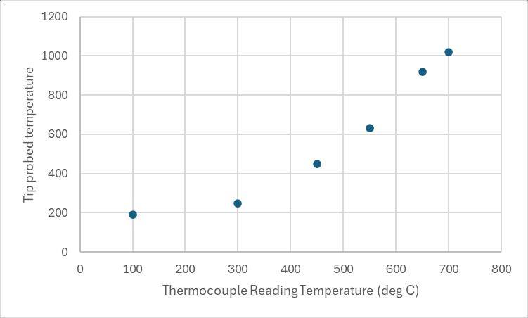
                                        thanks for the guidance. I think this is enough for a start. 🙂

                                        OwenDundefined 1 Reply Last reply Reply Quote 0
                                        • OwenDundefined
                                          OwenD @lynnmt
                                          last edited by

                                          @lynnmt

                                          Unrelated to the tuning, but I wonder if adopting a setup similar to hot wire tig welding would be beneficial in this application ?
                                          Essentially the wire has a current applied by an external DC power source (sometimes AC), with the bed being the ground.
                                          When a connection occurs during feeding, the wire is "pre heated" allowing for faster melting & higher deposition rates.
                                          The current used isn't enough that the wire can create an arc on its own.

                                          lynnmtundefined 1 Reply Last reply Reply Quote 0
                                          • lynnmtundefined
                                            lynnmt @OwenD
                                            last edited by

                                            @OwenD
                                            others have already done this.
                                            https://hackaday.io/project/169412-wire-3d-printer
                                            https://www.digitalalloys.com/

                                            it requires large currents and does not work with glasses or ceramics.
                                            neat process, but will not work for my application unfortunately.

                                            OwenDundefined 1 Reply Last reply Reply Quote 0
                                            • First post
                                              Last post
                                            Unless otherwise noted, all forum content is licensed under CC-BY-SA