Duet3D Logo Duet3D
    • Tags
    • Documentation
    • Order
    • Register
    • Login
    1. Home
    2. lynnmt
    • Profile
    • Following 1
    • Followers 0
    • Topics 1
    • Posts 34
    • Best 3
    • Controversial 0
    • Groups 0

    lynnmt

    @lynnmt

    7
    Reputation
    4
    Profile views
    34
    Posts
    0
    Followers
    1
    Following
    Joined Last Online

    lynnmt Unfollow Follow

    Best posts made by lynnmt

    • how to setup a hotend for directly printing metal and ceramic.

      The quick gist of what i am doing and why:

      I am developing an open source hotend for semisolid metal direct write and direct ceramic 3D printing.

      my hot end consists of a glow plug like the one I have modeled at this link, with a 0.5mm ID straight center bore(60mm deep)hole EDM drilled through it lengthwise. These glowplugs are capable of long term stable operation in air at up to about ~1500 C, and are essentially nonwetting and nonreactive to most nonferrous molten metals at temperatures below 1300 C. they are made of Si3N4-MoSi2 ceramic, which is an electrically semiconducting ceramic matrix composite, and they only heat at the tiny region at the tip, about 2.8mm OD, and ~2 mm long.

      Shameless plug

      i have a youtube video showing the hotend mounted and working on and ender 3 when we were clearing some bronze that got jammed inside it when I stupidly overheated the bronze and simultaneously pulled the feedstock wire out of the hotend, leaving behind a blob of oxide rich slag which had to be remelted and wicked out with a more refractory wire of silicon carbide.

      We use the EDM drilled ceramic glow plug as a combined heated nozzle +hotend+temperature sensor that is extremely fast, and has surface power density comparable to a torch flame(between 1 and 15 watt/mm^2 typical depending on what we are printing) to be able to rapidly heat and cool a a 24 AWG (0.522mm OD, 510 phosphor bronze) metal wire (with no nozzle constriction) to maintain the temperature between the solidus and liquidus for the wire, at the deposition region where the wire touches the build plate. Maintaining such temperature control requires extremely fast temperature cycling up and down(up to about 1000 degrees C/second) (more typical 350 degrees C /second) , and requires very sensitive temperature measurement(+- 1 degree C at a minimum..) to be able to respond to changes in flow conditions in time to maintain stable deposition.

      a little bit about what we are printing with:

      it helps to have metals that have a wide window between solidus and liquidus. 510 phosphor Bronze is one of the few easily available alloys that has a wide window. between 930 and 1060 C, about 130 degrees C.

      so we have opted to start by trying to print bronze from 24AWG (0.52mm) 510 phosphor bronze wire available on mcmaster.

      small wire diameter also helps because it reduces total mass flow requirements and reduces dead metal and risks for granular jamming in the hotend. small hole diameter in the hotend enables the high temperature of the heater to exclude air from the bore, and this provides a relatively anoxic environment inside the hotend which protects the metal from oxidation. the small mass of metal being deposited means that rapid quenching occurs on the build plate, and this means there is little time for oxidation, and for grain growth... because the metal is semisolid as printed, it develops about 3 orders of magnitude less internal stress than in approaches like WAAM.

      this all means that a single rather challenging machining operation was requried to make the ceramic glowplugs into suitable hotends, that is, EDM drilling a centerbored a 60mm X 0.5mm diameter through hole in the Si3N4 MoSi2 ceramic body of the glowplug.

      we have managed to obtain reliable operations for doing the manufacturing.
      we now just need to get control of the system which may require a few minimal firmware alterations...

      we have been aiming for a drop in mod for the ender 3 being the first thing we make and offer for a wider audience, if it works.

      The crux of the problem

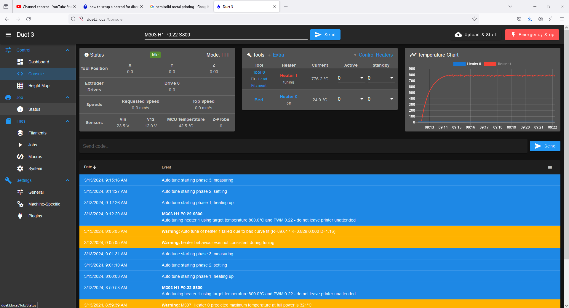
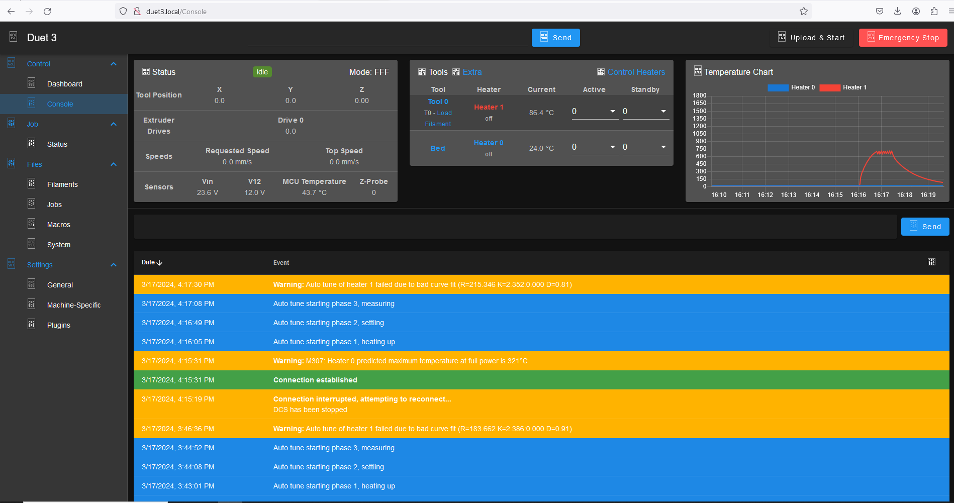
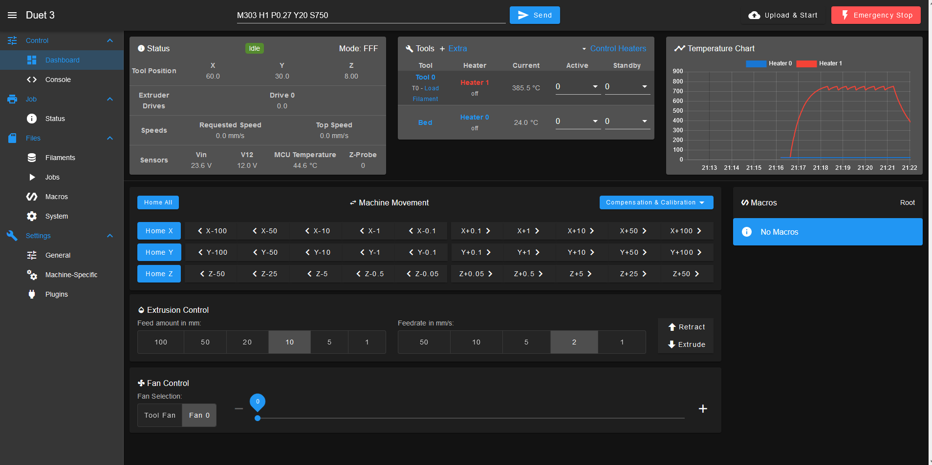
      I am having a lot of trouble getting the duet to cooperate and control these extremely high performing heaters. the PID tuning algorithm seems to be too slow to respond to them, and this trip heater faults.
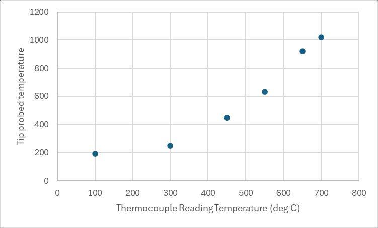
      I am also doing temperature sensing of the heaters by wrapping a type K thermocouple around the ceramic tip and slathering it in refractory cement. this appears to cause some amount of signal cross talk with the thermocouple amplifier MAX 31856 duet daughterboard. or something... I keep getting the error "fault on heater 1:sensor short to other wiring"
      but if I leave the printer to sit after clearing the fault, for perhaps 10-20 minutes, the thermocouple reads temperatures on the hotend heaters of ~30-45C. I can then attempt a PID tun or to enable the heaters, but the tune fails consistently when the overshoot is much larger than anticipated or for some other reason I have not identified.

      ## Basically I need help controlling the temperature of these heaters and making the necessary firmware adjustments to make their control reliable.

      I am not a firmware or software developer, please keep responses at the level of a 5 year old if at all possible...

      Any assistance is greatly appreciated. 🙂

      posted in Hardware dev
      lynnmtundefined
      lynnmt
    • RE: how to setup a hotend for directly printing metal and ceramic.

      @dc42 steady800Cautotune.PNG

      some images....the first is the requested screen capture.

      this last tune I screep caped had this warning:
      "Auto tune of heater 1 failed due to bad curve fit (R=61.202 K=0.807:0.000 D=1.59)"

      posted in Hardware dev
      lynnmtundefined
      lynnmt
    • RE: how to setup a hotend for directly printing metal and ceramic.

      @T3P3Tony
      the altered firmware from DC42 seems to be working perfectly.
      thanks!

      I will report back when we run our first tests of printing 510 phosphor bronze from mcmaster.
      https://www.mcmaster.com/9668K92/

      posted in Hardware dev
      lynnmtundefined
      lynnmt

    Latest posts made by lynnmt

    • RE: how to setup a hotend for directly printing metal and ceramic.

      @T3P3Tony
      the altered firmware from DC42 seems to be working perfectly.
      thanks!

      I will report back when we run our first tests of printing 510 phosphor bronze from mcmaster.
      https://www.mcmaster.com/9668K92/

      posted in Hardware dev
      lynnmtundefined
      lynnmt
    • RE: how to setup a hotend for directly printing metal and ceramic.

      @dc42

      thanks!
      is this linked repository available to be directly upgraded to from a networked SBC?
      Or should I copy in the firmware folder manually to the SBC and install it from a local directory by including in the sources list for APT?

      I have so far been unable to find this particular firmware using APT search.

      do you have a preferred way to do this?

      all the best,
      Michael Lynn

      posted in Hardware dev
      lynnmtundefined
      lynnmt
    • RE: how to setup a hotend for directly printing metal and ceramic.

      @dc42
      ce4f4153-cf7e-4614-b575-4b1e12c581a6-image.png

      So one of our project members, Shields experiments provided us a thermocouple isolator interposer for the duet thermocouple board.
      this allows us to use a thermocouple directly on the tip of the heater with no insulation and no stainless steel ring.

      Unfortunately, this also means that our model parameters are once again out of range...

      can you point me to the place in the firmware where I can adjust the model parameter range?
      I have no fear of finding and modifying it to make this work. 🙂

      posted in Hardware dev
      lynnmtundefined
      lynnmt
    • RE: how to setup a hotend for directly printing metal and ceramic.

      @OwenD
      others have already done this.
      https://hackaday.io/project/169412-wire-3d-printer
      https://www.digitalalloys.com/

      it requires large currents and does not work with glasses or ceramics.
      neat process, but will not work for my application unfortunately.

      posted in Hardware dev
      lynnmtundefined
      lynnmt
    • RE: how to setup a hotend for directly printing metal and ceramic.

      So after taking @dc42 suggestion and raising the temperature limit to 1750C,
      the Autotune (at 700 C target temperature and 0.27 pwm limit with Y20) worked and returned parameters:

      Heater 1: heating rate 44.460, cooling rate 0.824, dead time 1.70, max PWM 0.27, mode PID, calibrated at 23.6V
      Predicted max temperature rise 1918°C
      PID parameters: heating P2.4 I0.233 D2.8, steady P2.4 I0.499 D2.8

      This seems to be reliable enough given my janky current setup to transfer to the working printhead.

      We also characterized the offset temperature from the glowplug tip to the thermocouple y measuring the tip temperature with an identical type K thermocouple.

      here is the result
      38f93781-ccbd-4f0f-889b-89bd0fe312a5-image.png

      thanks for the guidance. I think this is enough for a start. 🙂

      posted in Hardware dev
      lynnmtundefined
      lynnmt
    • RE: how to setup a hotend for directly printing metal and ceramic.

      @dc42

      config.g

      ; Configuration file for Duet 3 MB 6HC (firmware version 3.3)
      ; executed by the firmware on start-up
      ;
      ; generated by RepRapFirmware Configuration Tool v3.4.1 on Fri Feb 23 2024 23:32:11 GMT-0600 (Central Standard Time)
      
      ; General preferences
      G90                                          ; send absolute coordinates...
      M83                                          ; ...but relative extruder moves
      M550 P"Duet 3"                               ; set printer name
      M918 P1 E4 F2000000                          ; configure direct-connect display
      
      ; Drives
      M569 P0.0 S0                                 ; physical drive 0.0 goes backwards
      M569 P0.1 S1                                 ; physical drive 0.1 goes forwards
      M569 P0.2 S1                                 ; physical drive 0.2 goes forwards
      M569 P0.3 S0                                 ; physical drive 0.3 goes backwards
      M584 X0.0 Y0.1 Z0.2 E0.3                     ; set drive mapping
      M350 X16 Y16 Z16 E16 I1                      ; configure microstepping with interpolation
      M92 X80.00 Y80.00 Z400.00 E93.00             ; set steps per mm
      M566 X1200.00 Y1200.00 Z24.00 E300.00        ; set maximum instantaneous speed changes (mm/min)
      M203 X9000.00 Y9000.00 Z180.00 E6000.00      ; set maximum speeds (mm/min)
      M201 X500.00 Y500.00 Z100.00 E5000.00        ; set accelerations (mm/s^2)
      M906 X800 Y800 Z800 E1000 I50                ; set motor currents (mA) and motor idle factor in per cent
      M84 S30                                      ; Set idle timeout
      
      ; Axis Limits
      M208 X0 Y0 Z0 S1                             ; set axis minima
      M208 X235 Y235 Z250 S0                       ; set axis maxima
      
      ; Endstops
      M574 X1 S1 P"io1.in"                         ; configure switch-type (e.g. microswitch) endstop for low end on X via pin io1.in
      M574 Y1 S1 P"io2.in"                         ; configure switch-type (e.g. microswitch) endstop for low end on Y via pin io2.in
      M574 Z1 S2                                   ; configure Z-probe endstop for low end on Z
      
      ; Z-Probe
      M950 S0 C"io5.out"                           ; create servo pin 0 for BLTouch
      M558 P9 C"io5.in" H5 F120 T6000              ; set Z probe type to bltouch and the dive height + speeds
      G31 P500 X0 Y0 Z3                            ; set Z probe trigger value, offset and trigger height
      M557 X60:215 Y30:195 S20                     ; define mesh grid
      
      ; Heaters
      M308 S0 P"temp0" Y"thermistor" T100000 B4092 ; configure sensor 0 as thermistor on pin temp0
      M950 H0 C"out0" T0                           ; create bed heater output on out0 and map it to sensor 0
      M307 H0 B1 S1.00                             ; enable bang-bang mode for the bed heater and set PWM limit
      M140 H0                                      ; map heated bed to heater 0
      M143 H0 S150                                 ; set temperature limit for heater 0 to 150C
      M308 S1 P"spi.cs0" Y"thermocouple-max31856"  ; configure sensor 1 as thermocouple via CS pin spi.cs1
      M950 H1 C"out1" T1                           ; create nozzle heater output on out1 and map it to sensor 1
      M307 H1 B0 S0.10                             ; disable bang-bang mode for heater  and set PWM limit
      M143 H1 S900                                ; set temperature limit for heater 1 to 900C
      
      ; Fans
      M950 F0 C"out7" Q500                         ; create fan 0 on pin out7 and set its frequency
      M106 P0 S0 H-1                               ; set fan 0 value. Thermostatic control is turned off
      
      ; Tools
      M563 P0 D0 H1 F0                             ; define tool 0
      G10 P0 X0 Y0 Z0                              ; set tool 0 axis offsets
      G10 P0 R0 S0                                 ; set initial tool 0 active and standby temperatures to 0C
      
      ; Custom settings are not defined
      
      ; Miscellaneous
      M501                                         ; load saved parameters from non-volatile memory
      T0                                           ; select first tool
      

      I have set the temperature limit to 900 C.
      why would there be a minimum limit for the model parameters to be accepted?
      my heater cannot be allowed to operate above about 1300 C in air for an extended period, or its resistance will drift.
      I set a lower limit, because the thermocouple has a large offset temperature and I dont know it exactly. so I set a conservative limit, as I wanted to avoid destroying my heater.

      posted in Hardware dev
      lynnmtundefined
      lynnmt
    • RE: how to setup a hotend for directly printing metal and ceramic.

      @dc42
      I have successfully upgraded to RRF 3.5.0-rc.3.
      Autotuning of my heater still fails with the warning

      running M303 H1 Y20 P0.27 S750 returns:

      "Autotune failed due to bad curve fit (R=53.131 K=0.801:0.000 D=1.25)

      If i then take the provided model parameters, and plug them into M307 as:
      M307 H1 R53.131 K0.801 D1.25
      this command returns

      Error M307 : Bad model parameters.

      The autotune makes a very nice curve, see picture here:
      66bc7655-cc32-4f60-a35d-120b175ef507-image.png

      Not sure what to make of this.

      posted in Hardware dev
      lynnmtundefined
      lynnmt
    • RE: how to setup a hotend for directly printing metal and ceramic.

      @lynnmt
      is this an unstable package release?

      also,
      will the instructions here be sufficient for making this firmware update or are there other sources to consider?

      https://docs.duet3d.com/User_manual/Machine_configuration/DSF_RPi#software-installation

      when I run the commands suggested for upgrading to unstable releases, here:
      sudo rm -f /etc/apt/sources.list.d/duet3d.list
      sudo bash -c "echo 'deb https://pkg.duet3d.com/ unstable armv7' > /etc/apt/sources.list.d/duet3d-unstable.list"

      my command prompt on SBC returns

      bash - "permision denied"

      posted in Hardware dev
      lynnmtundefined
      lynnmt
    • RE: how to setup a hotend for directly printing metal and ceramic.

      @dc42
      excellent. Thanks for running the test.
      I will try the upgraded firmware.
      A further question,
      is there some way to know what these heater limits are and to make them user adjustable without needing to compile firmware?

      all the best,
      Michael Lynn

      posted in Hardware dev
      lynnmtundefined
      lynnmt
    • RE: how to setup a hotend for directly printing metal and ceramic.

      @lynnmt Ah! I forgot to mention a important detail!

      the glowplug heater is PTC!

      posted in Hardware dev
      lynnmtundefined
      lynnmt