how to setup a hotend for directly printing metal and ceramic.
-
@lynnmt I think it is only for the model to work. Normally, it should be a real ”limit” here, and for the heaters wich I not did autotune (or failed, probably because of the same problem as yours now, and for wich I set the model parameters manually), I get some warnings like: ”your temperature may reach XXX degrees”, but this did not happened... yet.
M143 H4 S100 ; set temperature limit for heater 1 to 100CAnd the model:
M307 H4 R0.217 K0.124:0.000 D19.84 E1.35 S1.00 B1So the software warns me at start-up that based on my M307, and ... do not know what else, the heater will reach 176C. I could not care less, as it works, just an annoying message more.
-
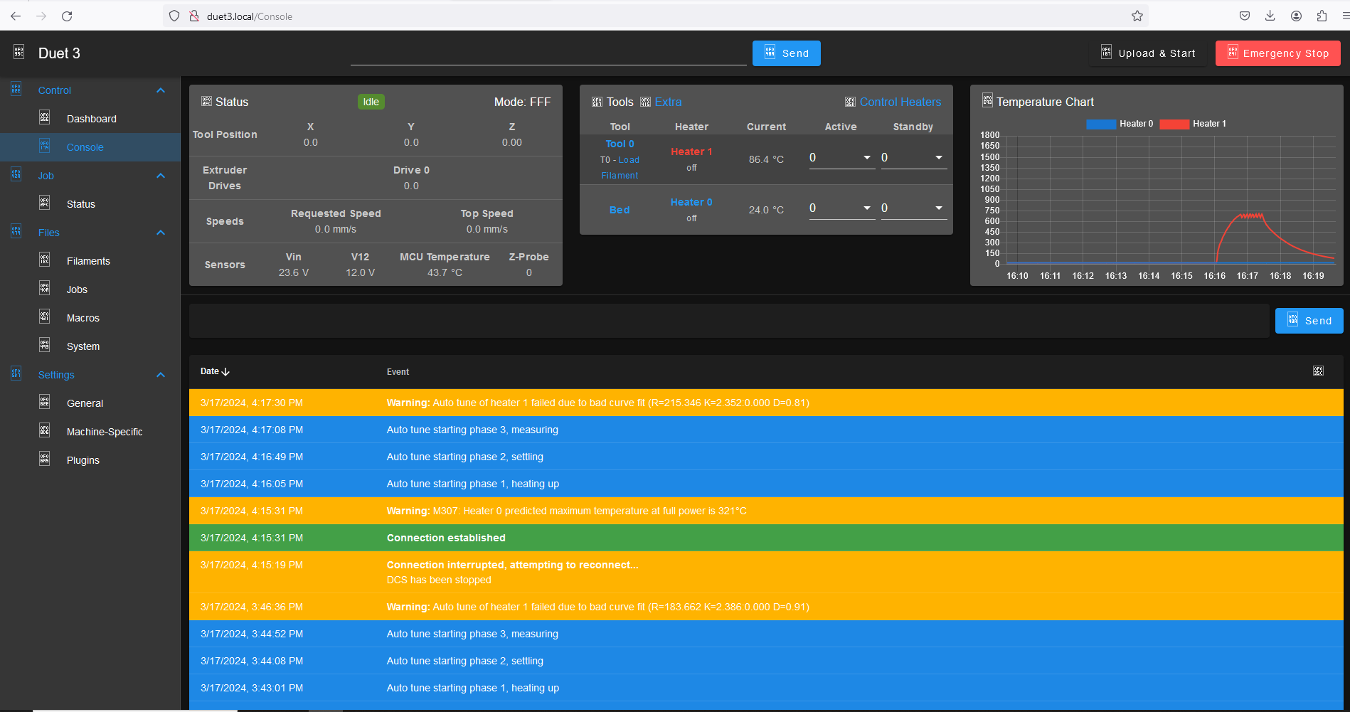
So after taking @dc42 suggestion and raising the temperature limit to 1750C,
the Autotune (at 700 C target temperature and 0.27 pwm limit with Y20) worked and returned parameters:Heater 1: heating rate 44.460, cooling rate 0.824, dead time 1.70, max PWM 0.27, mode PID, calibrated at 23.6V
Predicted max temperature rise 1918°C
PID parameters: heating P2.4 I0.233 D2.8, steady P2.4 I0.499 D2.8This seems to be reliable enough given my janky current setup to transfer to the working printhead.
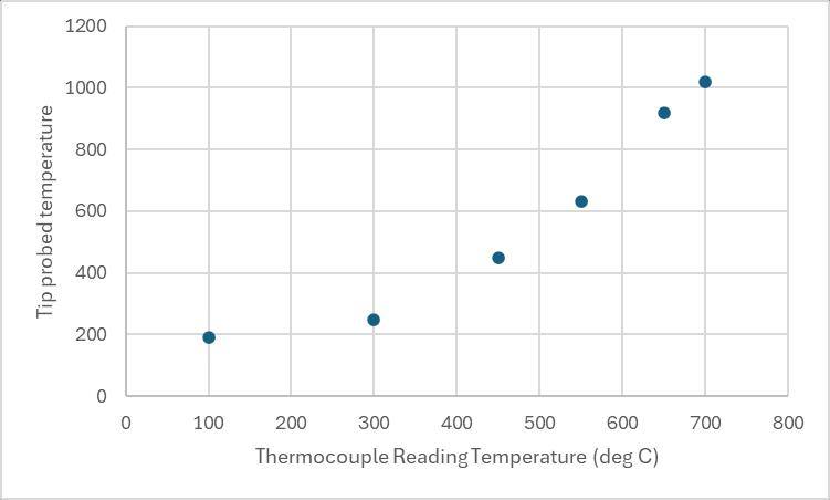
We also characterized the offset temperature from the glowplug tip to the thermocouple y measuring the tip temperature with an identical type K thermocouple.
here is the result
thanks for the guidance. I think this is enough for a start.
")
-
Unrelated to the tuning, but I wonder if adopting a setup similar to hot wire tig welding would be beneficial in this application ?
Essentially the wire has a current applied by an external DC power source (sometimes AC), with the bed being the ground.
When a connection occurs during feeding, the wire is "pre heated" allowing for faster melting & higher deposition rates.
The current used isn't enough that the wire can create an arc on its own. -
@OwenD
others have already done this.
https://hackaday.io/project/169412-wire-3d-printer
https://www.digitalalloys.com/it requires large currents and does not work with glasses or ceramics.
neat process, but will not work for my application unfortunately. -
@lynnmt
Those examples are using the current to melt the wire (akin to MIG welding), so they are nothing like TIG hot wire.
In hot wire TIG, the current through the wire is much lower and used only to aid melting the wire by getting it hot.
The main heat source is external. In TIG it's a high current arc carried via a tungsten electrode, but a heating cartridge would equally work.
Naturally it wouldn't work with non conductive materials.
Anyway, just a thought. -
So one of our project members, Shields experiments provided us a thermocouple isolator interposer for the duet thermocouple board.
this allows us to use a thermocouple directly on the tip of the heater with no insulation and no stainless steel ring.Unfortunately, this also means that our model parameters are once again out of range...
can you point me to the place in the firmware where I can adjust the model parameter range?
I have no fear of finding and modifying it to make this work. -
@lynnmt the validation of model parameters is in function FopDt::SetParameters in file FOPDT.cpp.
However, I decided to remove the check on maximum temperature increase when validating parameters, which should resolve the problem for you. You will still see a warning if the estimated maximum temperature is high. I have also provided a more detailed error message when validation of model parameters fails. You can find the latest 3.5.0-rc.3+4 firmware binaries with these changes included at https://www.dropbox.com/scl/fo/yzchzlyxmxlzywjawqflu/h?rlkey=tl7dfs75yozhfgpze0jnkn32n&dl=0.
Duet WiFi hardware designer and firmware engineer
Please do not ask me for Duet support via PM or email, use the forum
http://www.escher3d.com, https://miscsolutions.wordpress.com -
thanks!
is this linked repository available to be directly upgraded to from a networked SBC?
Or should I copy in the firmware folder manually to the SBC and install it from a local directory by including in the sources list for APT?I have so far been unable to find this particular firmware using APT search.
do you have a preferred way to do this?
all the best,
Michael Lynn -
@lynnmt the drop box firmware builds are experimental and not available over apt. please do the following:
- ensure you upgraded to the latest unstable release via apt (3.5rc3)
- use DWC up upgrade to the firmware files shared in dropbox (pick the /bin file or files for the boards in your system, do to system-> Upload system files) DWC will warn you then you should only so this if asked to do so.
-
@T3P3Tony
the altered firmware from DC42 seems to be working perfectly.
thanks!I will report back when we run our first tests of printing 510 phosphor bronze from mcmaster.
https://www.mcmaster.com/9668K92/