Connecting external steppers - Going from 1XD to a 6XD mainboard
-
Hey everyone.
I'm working on converting a new printer to a Duet.
The printer is a Creatbot D600 Pro that uses two different kinds of stepper driver for Z and for X/Y.I already did the conversion once, but I previously used a 6HC (which was stupid) with three 1XD. And now I moved to a 6XD board but i'm having problems with making the motor moves.
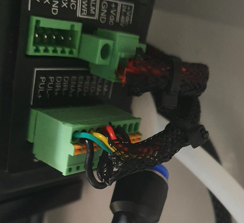
This is the input for the Z stepper driver which is a TB6600 :
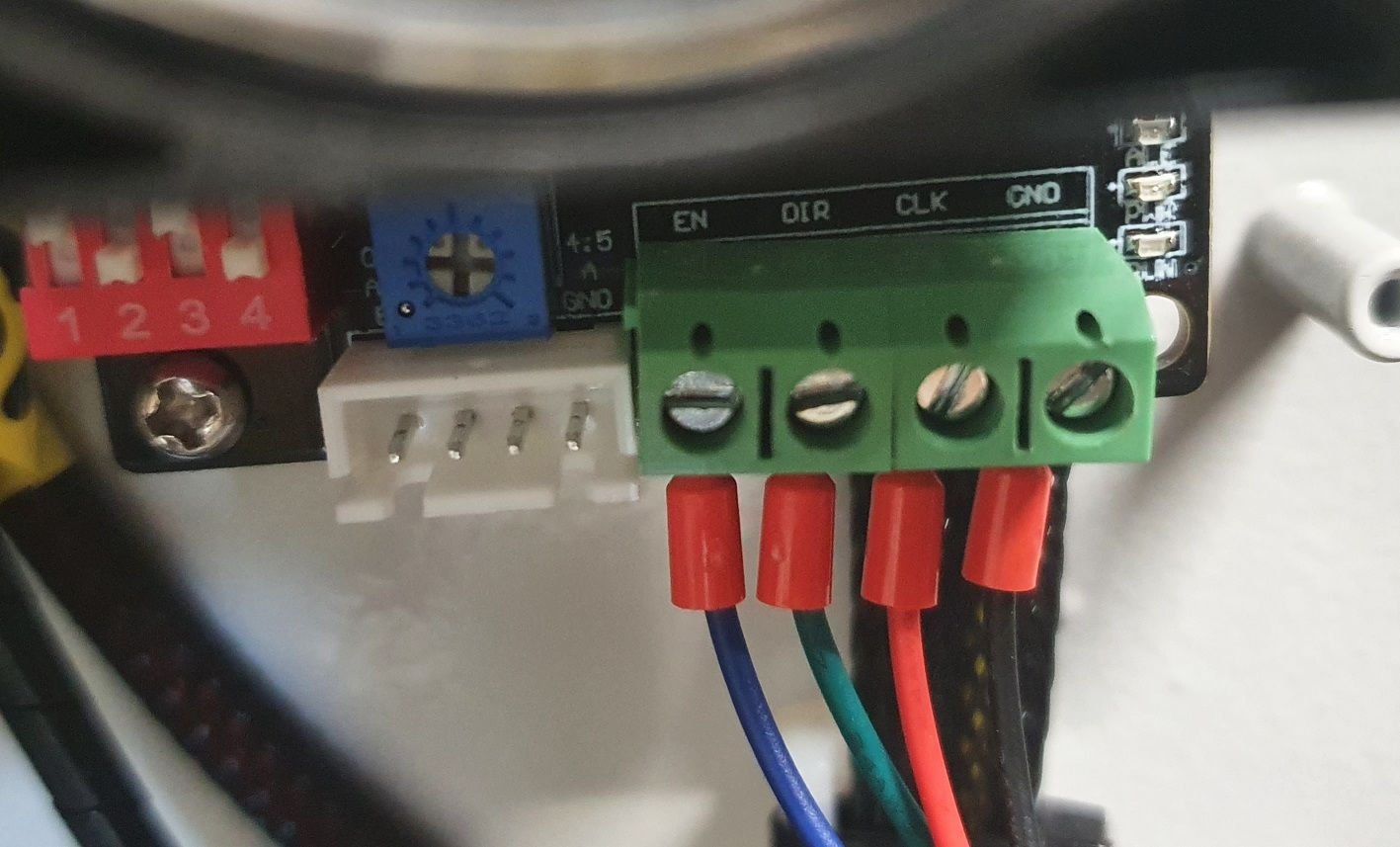
And this is the input for the X and Y stepper driver which are this reference. Note that the connections from factory are made with common grounds (to PUL-, DIR- and EN-) and the signal are passed to the PUL+ DIR+ and EN+.
I managed to make it work with my previous machine and the 1XD boards with connections like these :
External stepper for Z TB6600 -> 1XD Board
CLK -> D0_STEP (+)
DIR -> D0_DIR (+)
EN -> D0_EN (-)
GND - > GND (on the IO0)External stepper for X and Y -> 1XD Board
PUL+ -> D0_STEP (+)
DIR+ -> D0_DIR (+)
EN+ -> D0_EN (-)
PUL-, DIR- and EN- > GND (on the IO0)Now I moved to a 6XD board and there are no longer the DIR+ and STEP+ pins on the 6XD board. So I did this :
External stepper for Z TB6600 -> 6XD Board
CLK -> D0_STEP (-)
DIR -> D0_DIR (-)
EN -> D0_EN (-)
GND - > GNDExternal stepper for X and Y -> 6XD Board
PUL+ -> D0_STEP (-)
DIR+ -> D0_DIR (-)
EN+ -> D0_EN (-)
PUL-, DIR- and EN- > GND (on the IO0)It does not work. Nothing moves. I understand the problem that I have is that I only have low signals (-) and no 5V in my wiring, but I don't know how to do it differently...
I checked with a multimeter and the EN signal (from EN- to 5V) and DIR signal (from DIR- to 5V) are working as expected (going from 0 to 5V, when I turn motor on or when I switch direction in the moves). So I don't think it's a firmware issue.
I have a few question :
-
There is a bridge that can be set in the firmware, is it the same as changing the R parameter in the M569 command ?
-
In the 6XD documentation here, there is this sentence :
"To connect a Pololu/StepStick/similar driver to the 6XD a 10K pullup resistor is needed from the Step/Dir/En lines to +5V"
This might be what I need to do, but I don't understand what a "pullup resistor" is and how I should connect them.
I also found this sentence :
"The Step and Dir outputs from the 6XD are either low (when "on") or floating/high-impedance when "off""
From my understanding, it's related to above so the step and dir outputs are at GND when low (on) and are just "whatever" when off ? And the "pullup resistor" would make the "whatever" be 5V when off ? Did I understood that correctly ? -
For the X and Y motors which have all poles (DIR+/DIR-, STEP+/STEP-, EN+/EN-), I see on the same 6XD documentation that it's recommended to have the common 5V to the DIR+ STEP+ and EN+. It's different from the wiring that I have from factory and I'd rather keep them that way if possible as the motor are very hard to access and would recquire a lot of disassembly to modify this wiring... Is it possible to make it work with a 6XD without changing these cables ? Maybe with the same pull up resistor trick ?
Thanks in advance for your help.
-
-
@Shoki I think your wiring is wrong on both drivers. The easier one to fix is the External stepper for X and Y. You have:
External stepper for X and Y -> 6XD Board
PUL+ -> D0_STEP (-)
DIR+ -> D0_DIR (-)
EN+ -> D0_EN (-)
PUL-, DIR- and EN- > GND (on the IO0)Unfortunately, it's not going to work with that wiring. You need to wire it:
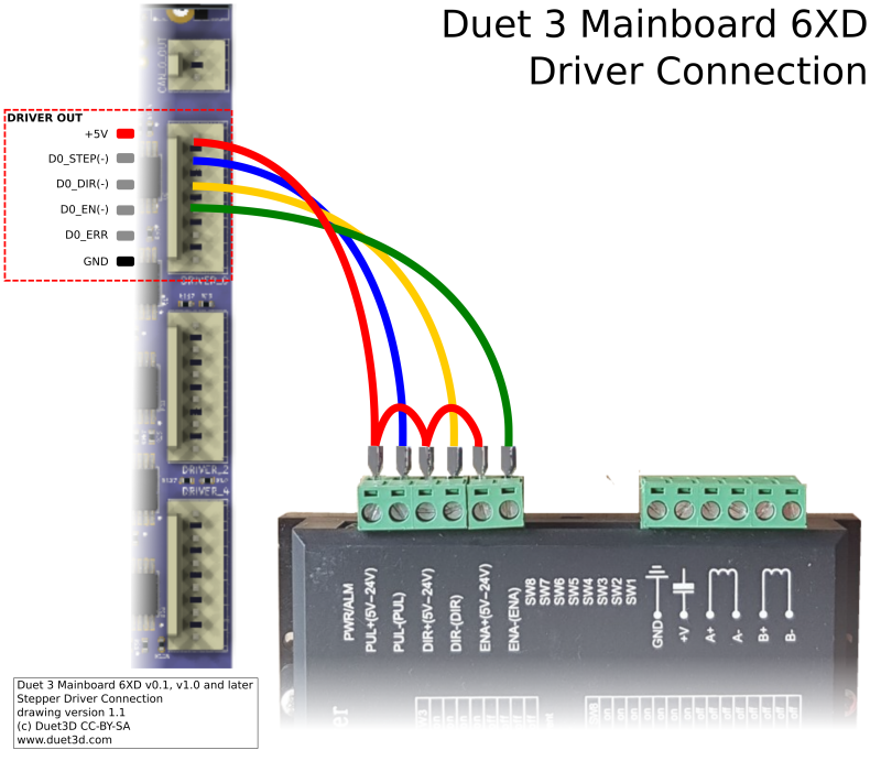
6XD Board -> External stepper for X and Y
5V -> PUL+
5V -> DIR+
5V -> EN+
D0_STEP (-) -> PUL-
D0_DIR (-) -> DIR-
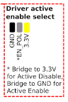
D0_EN (-) -> ENThis should give the driver a +5V signal on each connection, because the 6XD switches each output on the GND side of each pin. The 1XD . I would expect that the drive is enabled with no signal, and disabled with +5V, so I think you need to set the 'Driver active enable select' jumper to bridge to 3.3V, for 'Active Disable'; ie when the enable pin is active, the +5V signal is grounded, which disables the drive.
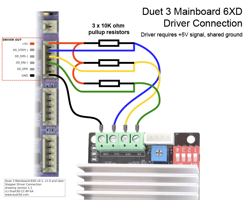
The Z stepper driver TB6600 is a little more complicated. Yes, You need to 'pull up' the signals. The driver has three inputs for a +5V signal, and a common GND. Because each pin on the 6XD is switching to GND, the TB6600 does not receive a signal. For each signal, you need to wire a 10K ohm resistor between 5V and the signal pin, and then take the output to the driver, like this:
Again, the driver will probably be disabled with a +5V signal, but in this case 'activating' the enable pin grounds 5V, so no 5V signal is sent to the drive. Ideally you would move the 'Driver active enable select' jumper, but this would mess up the configuration for the X and Y driver. Either disconnect the enable wire, so it is permanently enabled, or change the M569 R parameter for this driver.
There are some additional caveats to running the driver like this. From @dc42 :
- Unfortunately the 6XD isn't great for driving that board directly, assuming it needs positive-going step pulses, because the 6XD generates negative-going step pulses in this configuration. He would need to use the pullup resistor and then add an inverter between the step output and the driver. Otherwise there may be a risk of a step being in the wrong direction when the direction changes.
- If the driver samples direction and steps on the leading edge of the step pulse, it will be OK without an inverter. If it uses the trailing edge, it will need an inverter (check TB6600 driver specification)
- If you need an inverter, you only need it on the step output, because Enable can be flipped using M569 R parameter, and direction can be flipped using M569 S parameter.
You could possibly wire the X and Y drivers with the pull-up resistors, but I think with the above caveats it may give you problems when changing direction, though it does depend on the driver.
Ian
Bed-slinger - Mini5+ WiFi/1LC | RRP Fisher v1 - D2 WiFi | Polargraph - D2 WiFi | TronXY X5S - 6HC/Roto | CNC router - 6HC | Tractus3D T1250 - D2 Eth
-
-
@droftarts Hi
Thank you very much for your reply.
I had time this week to test your solutions.For X and Y, everything is working perfect. I realised the connector on the motor sides could be disassembled so it in the end it was quite easy to modify it there.
Regarding the Z motor driven by the TB6600, I tried your solution and it does not seem to work.
- I checked my wiring multiple times and everything seems like on your diagram.
- I checked the value of my resistor, they are 10k.
- I tried to change the M569 R parameter, no difference.
- I checked what I was getting on the EN/DIR/CLK at the TB6600 terminal : almost everything seems fine, signal goes from low to high on EN when I turn motor on (with the correct M569 R parameter), and signal switches on DIR when I switch the direction command. Only problem is : signal is not at 5V but at 1.4V which is probably my problem... I also checked what I was getting on the other side of the resistors and I did have 5V as expected.
- I tried to connect the X motor to this driver (to check if wasn't a config problem), and once I switched the M569 R parameter, X was working (when moving in Z), which is what I expected.
Any guess on why are my signals too low with this wiring ?
5V lane from the 6XD is not strong enough to pull the signal higher ? -
@Shoki I have another solution since I had to install a 3HC, it's just to connect the motor directly to the 3HC board...
The motor is this one, and it's rated for 3A so I can use a current of 75% of this rated current so around 2200 : M906 Z2200
https://cpdxkcnc.com/products/stepper-motor-nema23-76mm-30a-2nm-57hs76-3004a08-d21-05-569But I'm still interested in the solution to the TB6600 since I could use a free motor slot on my 3HC, and I don't want to have to buy a 1HCL or a second 3HC for it...
-
@Shoki my guess is that the TB6600 driver inputs have pulldown resistors of about 3.9K which are fighting with the 10K pullup resistors. You could try reducing the 10K pullup resistors to 1K.
-
@Shoki To add to what @dc42 said, a 1K ohm pullup should give a voltage of around 4V for the signals. This should be enough; the TB6600 datasheet has the input voltage on CW/CCW, CLK, and ENABLE (as well as other pins) as between -0.2V to 0.8V for low, and between 2V to 5.5V for high, which explains why 1.4V doesn't work, but 4V should. See top of page 5 here: https://www.mouser.com/datasheet/2/408/TB6600HG-483084.pdf
I think you have an MKS TB6600 board. The files for this are available here: https://github.com/makerbase-mks/MKS-Big-Current-Driver/tree/master/MKS TB6600-Black
There are some resistors on each input that can be seen in the schematic, labelled R6, R8 and R9, but unfortunately they don't list the values of components.
https://github.com/makerbase-mks/MKS-Big-Current-Driver/blob/master/MKS TB6600-Black/MKS TB6600(Black) V1.1_001/MKS TB6600(B)lack V1.1_001 SCH.pngIan