Duet3D Logo Duet3D
    • Tags
    • Documentation
    • Order
    • Register
    • Login

    Makergear(rambo 1.4) to Duet 3 mini wifi

    Scheduled Pinned Locked Moved
    Duet Hardware and wiring
    3
    5
    119
    Loading More Posts
    • Oldest to Newest
    • Newest to Oldest
    • Most Votes
    Reply
    • Reply as topic
    Log in to reply
    This topic has been deleted. Only users with topic management privileges can see it.
    • Theboz1419undefined
      Theboz1419
      last edited by

      Trying to get an headstart on making the transition to a Duet board and I am trying to find some good information about the wiring. For the Duet it's not an issue, but for the Rambo every diagram I find they only post a wire color code for each connection and I'm not finding anything that corelates to the Duet.

      For instance:

      For the drives on the Rambo, it says Red, Green, Yellow, Blue(awesome for colorblind people, lol)

      And of course,

      Duet

      Black(A+)Green(A-)Blue(B+)Red(B-)

      Which wires go with which?

      I would love to find a Rambo 1.4 that had the A-,B-,A+,B+,......ect.. for each wire connection, but I have yet to find one.

      Any help much appreciated, thanks

      dc42undefined droftartsundefined 2 Replies Last reply Reply Quote 0
      • dc42undefined
        dc42 administrators @Theboz1419
        last edited by

        @Theboz1419 what colours are the wires where they emerge from the motors?

        Duet WiFi hardware designer and firmware engineer
        Please do not ask me for Duet support via PM or email, use the forum
        http://www.escher3d.com, https://miscsolutions.wordpress.com

        1 Reply Last reply Reply Quote 0
        • droftartsundefined
          droftarts administrators @Theboz1419
          last edited by

          @Theboz1419 For motor wires, just test which pair of wires is each phase: https://docs.duet3d.com/User_manual/Connecting_hardware/Motors_connecting#identifying-the-stepper-motor-phases

          Then wire the phases to the stepper driver: https://docs.duet3d.com/User_manual/Connecting_hardware/Motors_connecting#using-the-internal-drivers

          Unfortunately there's no standard wire colouring on stepper motors, so it's best to test them.

          Ian

          Bed-slinger - Mini5+ WiFi/1LC | RRP Fisher v1 - D2 WiFi | Polargraph - D2 WiFi | TronXY X5S - 6HC/Roto | CNC router - 6HC | Tractus3D T1250 - D2 Eth

          Theboz1419undefined 1 Reply Last reply Reply Quote 0
          • Theboz1419undefined
            Theboz1419 @droftarts
            last edited by

            @droftarts Ty I figured as much from looking at the Rambo board aleast I know which two pair are connected together.

            droftartsundefined 1 Reply Last reply Reply Quote 0
            • droftartsundefined
              droftarts administrators @Theboz1419
              last edited by

              @Theboz1419 It looks like the Rambo is wired in the same way, ie one pair on the left hand pins, the other pair on the right:

              alt text

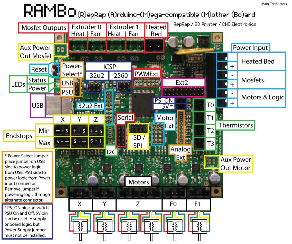
              Don't worry about the which pair goes where for motor direction, as this is easy to change in the config.g file: https://docs.duet3d.com/en/How_to_guides/Commissioning#h-10-check-stepper-motors

              Ian

              Bed-slinger - Mini5+ WiFi/1LC | RRP Fisher v1 - D2 WiFi | Polargraph - D2 WiFi | TronXY X5S - 6HC/Roto | CNC router - 6HC | Tractus3D T1250 - D2 Eth

              1 Reply Last reply Reply Quote 0
              • First post
                Last post
              Unless otherwise noted, all forum content is licensed under CC-BY-SA