Support for RS485 on Duet 6XD and 6HC
-
@dc42
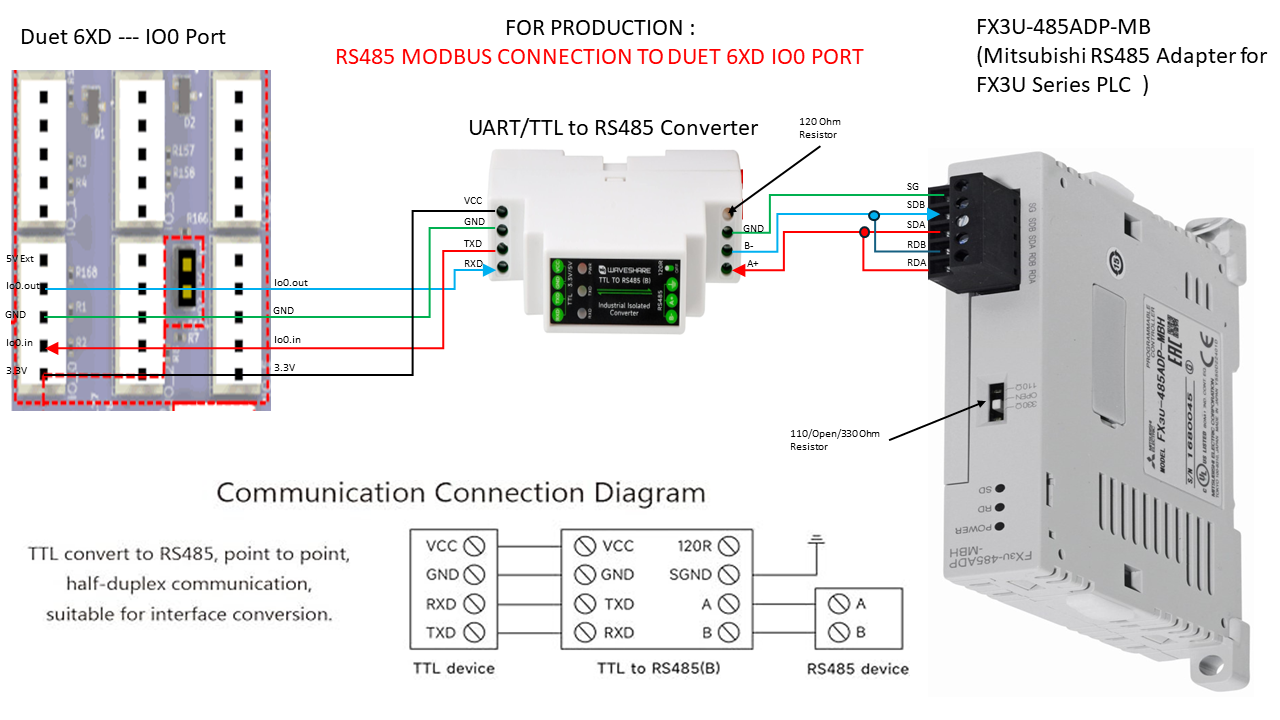
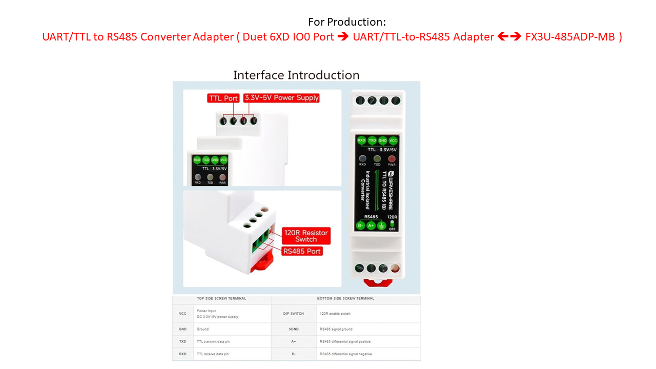
Currently with existing boards Would such a TTL (UART) to RS485 Converter Compatible with 3.3V and 5.0V signals work plus Spare IO (IO0 or IO1 ) port on Duet 6XD ?Below is Option 2: Using already existing RRF 3.5.2 CAN support by utilizing CAN0 AUX Port i.e Duet 6XD CAN0 AUX Port <==> CAN-RS485 MODBUS Converter <==> FX3U-485ADP-MB
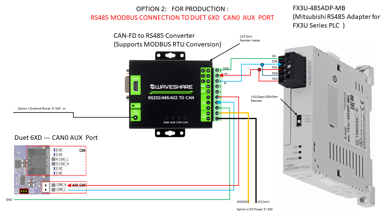
Below are the links to the adapters or converters for the 2 options:
CAN-to-RS485 Converter:
https://www.amazon.ca/dp/B0CSFH8QTN/?coliid=I35EGBMWD8HST8&colid=2QAEOOXW12HBB&psc=1&ref_=list_c_wl_lv_ov_lig_dp_itUART(TTL) To RS485 (B) Converter
https://www.amazon.ca/gp/product/B0BQFB7JCK/ref=ppx_yo_dt_b_search_asin_title?ie=UTF8&psc=1 -
@developeralgo222 yes that board looks good, although it's more complicated than RS485 boards that I have used before.
-
@dc42 As for communications commands from Duet 6XD to the electric feeder using the above setup ( RS485 Converter + IO0 Port ) . Can you please elaborate using RRF 3.5.2 commands with an example of a simple communication ?
-
@dc42, @T3P3Tony ,@droftarts Also what is the Maximum UART Port Speed that IO0 or IO1 can handle on Duet 6XD since i think default UART clock is 3MHz but Apparently UART CLOCK can go as high as 100MHZ. The maximum baud rate is clock/16.
So what is the Maximum Speed of UART Port on Duet 6XD without corruption of data ? 115200 bps ?
-
@developeralgo222 maximum transmission speed is much higher than that. However, it you try to receive data above about 57600 baud then you may suffer character loss because of interrupt latency.
-
@dc42 so what would be the recommended fastest baud rate to use with Duet 6XD?
-
@developeralgo222 also is it possible for one of your devs to add the support for RS485 MODBUS RTU to the unofficial dev version of RRF 3.5.2+ or 3.6 dev and I will act as tester for it because I really have an urgent huge need for RS485 MODBUS RTU for Duet 6XD or if one of your devs can provide the code , I can try and compile a dev version to use while waiting for the support to be included in official “After” RRF 3.6 version. I am really desperate to get this done , I need to control and communicate to over 60+ Electric SMT feeders using RS485 MODBUS RTU. This is really , really urgent , time is not on my side
-
@developeralgo222 I have just returned from holiday. My immediate priority this week is to fix bugs in 3.6 that our alpha testers have reported. When that's done I may get time to implement Modbus support in 3.6.
-
@dc42 , Thanks , i hope you got well needed rest on your vacation and you can get time to work on this. I understand the priority but our very Large project is now at a standstill, We are a large project completely based on Duet 6XD & 3HC products with our Total cost into Tens of thousands of $$$$$. we can't get it working without RS485 MODBUS RTU communications from Duet 6XD being supported. I am willing at moment to be one of the Alpha testers for 3.6.x with this RS485 MODBUS RU enabled.
-
@developeralgo222 I've put a preliminary build of RRF 3.6.0 for the 6XD with experimental Modbus RTU support at https://www.dropbox.com/scl/fo/868isq8kjcmgy1k7z7b3g/ADwxJUoidmE1XRYFZWMdCWk?rlkey=w8imtto9wirwitm5ac2xamxap&dl=0. I've only tested reading input registers, and only from one Modbus device. However as I won't be able to work on this again until next week, I'm making it available in case it is of any use to you.
To use Modbus:
- Connect a UART to RS485 converter to IO0 or IO1 of the 6XD
- Use the new S7 parameter and optionally the new C parameter of the M575 command to set the chosen port to Modbus mode, set the baud rate, and set the port to drive the Tx/!Rx input of the RS485 transceiver if required (that can be any other io#.out port)
- Use the new M260.1 command to write Modbus registers and/or the new M261.1 command to read Modbus input registers. Note, the M261.1 command V parameter is not implemented yet.
-
@dc42 Do you have a recommendation for a suitable converter? Most of the ones on Amazon seem to use automatic switching. This one seems to have enable pins: https://www.amazon.co.uk/WINGONEER-MAX485-Module-RS-485-Development/dp/B06XHHWLMW
-
@dc42 i will continue testing
-
-
i am testing with the following GCODE. Can you review to see if i am doing it correctly
M575 P1 B115200 S7  ; Set Serial comms parameters TX & RX
M260.1 P1 A1 R42 B1 ; Modbus Write to registers / Coils
M261.1 P1 A1 R42 B2 ; Modbus Read from Holding or Input registers / Coils
Below is:
RS485 Serial Connections Configurations on the PLC MODBUS RTU Side:
Modbus Slave Address (PLC): 1 Comm Mode : RS485 Modbus RTU Parameters: 115200, 8Bit, None, 1Bit i.e Baudrate : 115200 Length: 8 Parity : None Stop Bits: 1 Hardware Control: Flow Control Mode: No DTR: Enable RTS: Enable -
@developeralgo222 you only need one M575 P1 command, and the C parameter should only be used if your RS485 adapter has a Tx/Rx control input.
The V parameter of M261.1 is not yet implemented.
-
@dc42 as edited above ?
-
@developeralgo222 yes, if your RS485 adapter does automatic Tx/Rx switching, and you want to write 1 word with value 1 to register 42 and then read registers 42 and 43.
It might be a good idea to try with a lower baud fate initially e.g. 19200. The automatic Tx/Rx switching will probably only work over a range of baud rates. 9600 and 19200 are commonly used for Modbus RTU.
-
@dc42 , i managed to have it working at 115200. Need to go through simple tests
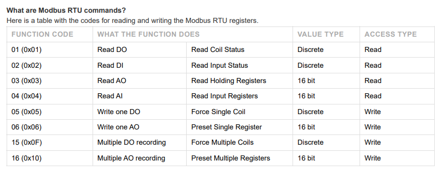
As per your statement above so far Function Code:
0x03 (Read Holding registers ) and 0x04 (Read input registers ) are working and i can also write to a single Register but i can't seem to be able force a single coil to ON (1) or OFF (0) directly
-
@developeralgo222 FX3U MODBUS Serial Communication Edition.pdf
If you review pages 55 - 75 & 95 on the PDF that has Modbus Format & address mapping for the device i have FX3U
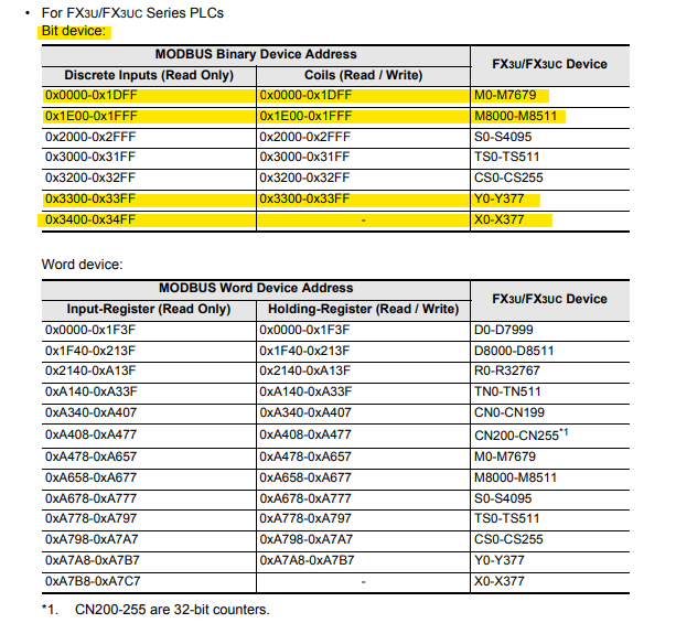 . I am trying to Write a single Coil to turn it ON(1) of OFF (0)
; Write to a single coil  Mxxx   e.g M41 (which has address 0x0029)  in order to turn it ON(1) = FF00  or OFF(0) = 0000

M260.1 P1 A1 R0x0029  B1

; Read a  single coil M41 (which has address 0x0029)  in order to turn it ON(1) = FF00  or OFF(0) = 0000

M260.1 P1 A1 R0x0029  B1
i don't seem to be able to format it correctly with Duet 6XD, any help on the formatting. i don't get errors but seem to be writing to correct Register
M260.1: Modbus write registers
Supported from firmware version 3.6Write data to a Modbus slave device.
Parameters
- Pnn -- Serial port to send/receive through, numbered as in M575 (1 = first aux port, 2 = second aux port). The port must already have been set to Modbus mode using M575.
- Ann -- Modbus slave device address
- Rnn -- First Modbus register number to send data to
- Bnn:nn:nn... --- 16-bit words to send
is the register number Rnn in Hexadecimal or decimal ? i presume it should be in Hex format ? what is the correct format , can you give an example using Coil M41 in my case . Note: i am able to turn it ON or OFF using Modbus RTU connection from my laptop or manually on the FX3U config app
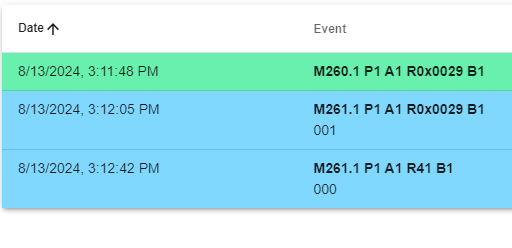
Here is some snapshot captures (Request & Response ) of the MODBUS communications between MODBUS Master (Open Modscan on a PC ) and Slave ( Mitsubishi FX3U-48MR PLC with FX3U-485ADP-MB Adapter) when testing various functions:
-
@developeralgo222 RRF doesn't yet support writing coils or reading discrete inputs, I only implemented writing registers, reading input registers, and reading holding registers.
Your document gives register numbers in hex. RRF takes parameters in decimal by default, but you can use hex numbers like this:
M260.1 P1 A1 R{0x0029} B1