G30 Probing in Positive Z Direction - Seeking Solutions
-
Hi everyone,
I've been working on setting up my tool length measurement, but I’ve run into a problem. The G30 command moves the Z-axis in the negative direction (down), but I need the probing to occur in the positive Z direction (upwards).
Does anyone have any suggestions or know of a way to configure G30 (or another command) to probe upwards instead of downwards?
Any advice or workaround would be greatly appreciated!
-
@an-andrew what are you trying to achieve? Doesn't sound like a typical 3d printer implementation
-
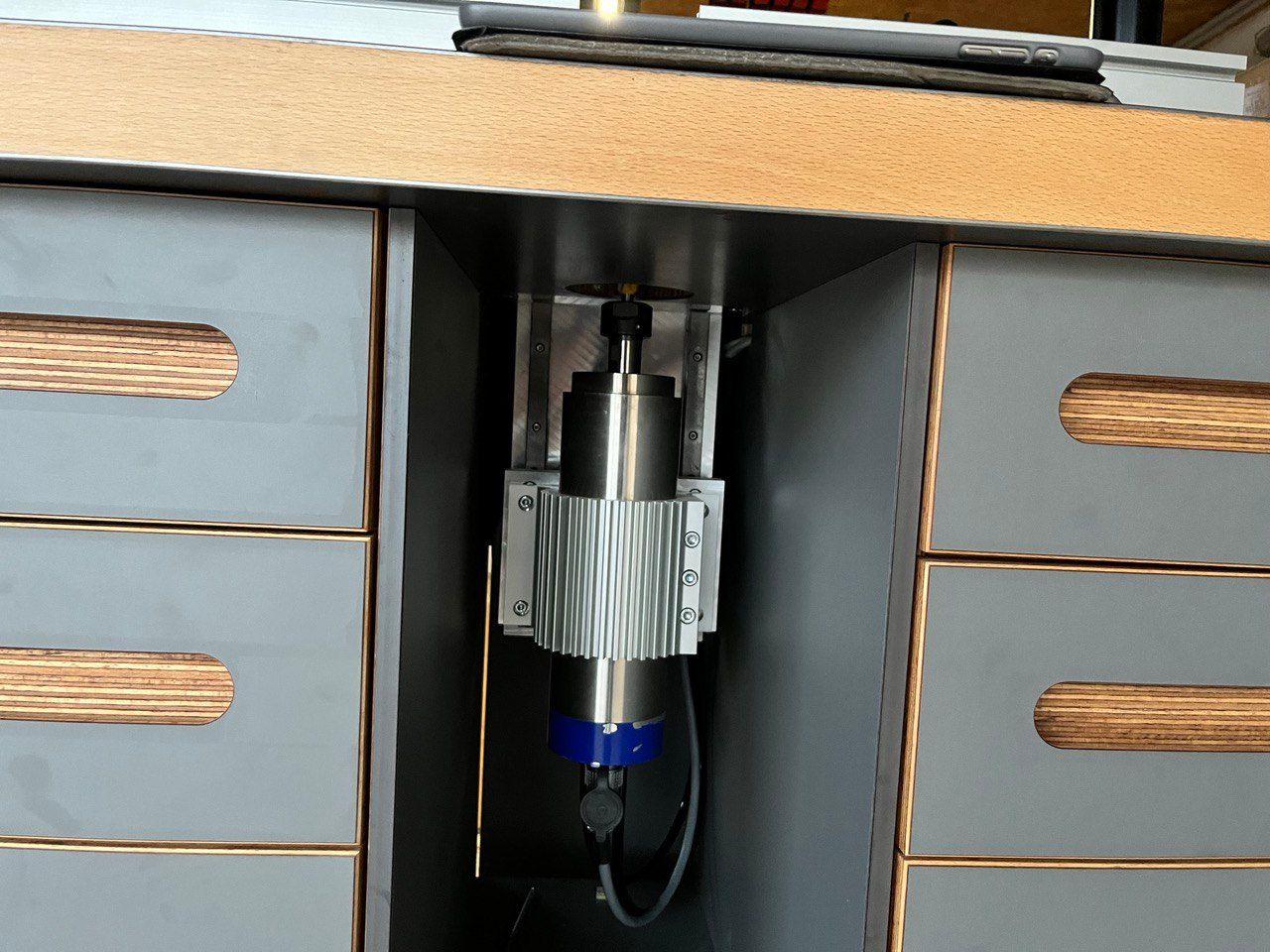
@jay_s_uk That's correct. I’ve built a router table, and now I need a tool length measurement system.
-
@an-andrew maybe G1 H3 or G1 H4?
or G38 might be better?Owns various duet boards and is the main wiki maintainer for the Teamgloomy LPC/STM32 port of RRF. Assume I'm running whatever the latest beta/stable build is
-
@jay_s_uk Thank you for the suggestion, but I still can’t see the solution. Could you provide an example code?
-
@an-andrew It would be helpful if you shared your config.g, so we can see how any probes and endstops are currently set up. Also, what do you want to actually probe up to? I don't see anything the tool is going to touch off, either a plate or endstop.
You could use a touch-off probe, like those used on CNC machines, where you attach a conductive clip to the tool, and it makes a circuit when it touches a plate. The plate is removable, as it's usually used on CNC machines to measure where the workpiece is. The plate could sit level with the router table, and you could measure from the Z axis home (when the spindle is all the way down) to the point where the end of the tool is level with the table.
Or you could put an fixed endstop of some form at maximum Z, and measure up to that, though there's a greater risk of driving straight through that!
Either way, as @jay_s_uk suggested, G1 H3/H4 or G30.# would let you measure the distance, and work out the length of the tool. I think we need to have a better understanding of your intention to provide example code.
G1 H3 and G1 H4 movements are described here: https://docs.duet3d.com/en/User_manual/Reference/Gcodes#g0g1-h-and-s-parameter
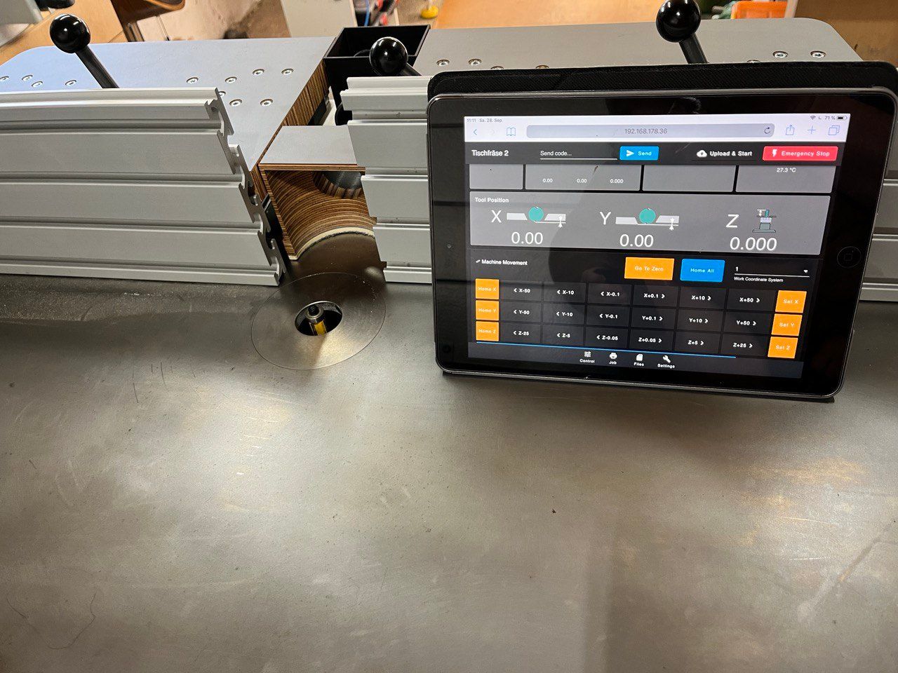
G38.2/3/4/5 are described here: https://docs.duet3d.com/en/User_manual/Reference/Gcodes#g382-straight-probeAlso, nice customisation of DWC!
Ian
-
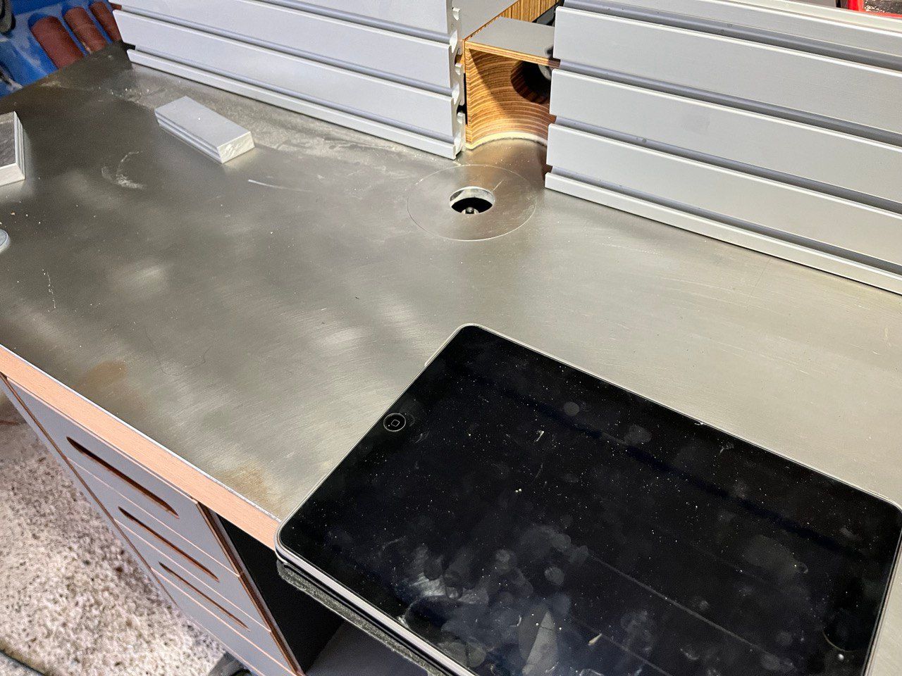
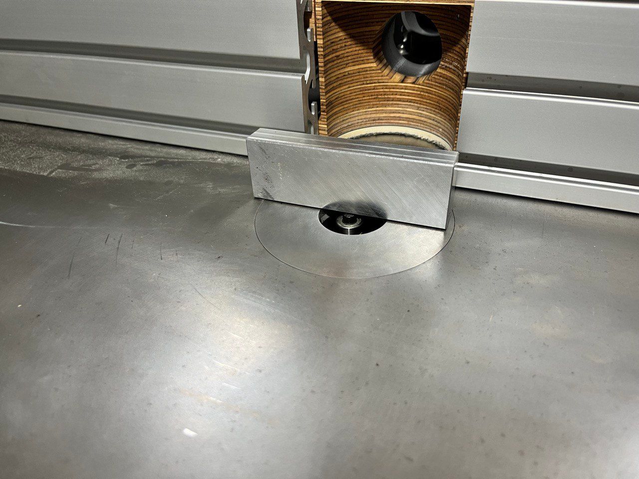
@jay_s_uk I simply want to place a metal part over the opening. The spindle is grounded and connected to GND, and the circuit will be closed via the table. The cable attached to the table plate is not visible and is connected to an input.
my config
; Configuration file for Duet WiFi (firmware version 3.3)
; executed by the firmware on start-up
;
; generated by RepRapFirmware Configuration Tool v3.3.14 on Sun Nov 20 2022 22:13:01 GMT+0100 (Mitteleuropäische Normalzeit)

; General preferences
M453
G90                                            ; send absolute coordinates...
M83                                            ; ...but relative extruder moves
M550 P"Tischfräse 2"                           ; set printer name

; Network
M552 S1                                        ; enable network
M586 P0 S1                                     ; enable HTTP
M586 P1 S0                                     ; disable FTP
M586 P2 S0                                     ; disable Telnet

; Drives
M569 P0 S0                                     ; physical drive 0 goes forwards
M569 P1 S0                                     ; physical drive 1 goes forwards
M569 P2 S0                                     ; physical drive 2 goes forwards
M584 X0 Y1 Z2                                  ; set drive mapping
M350 X16 Y16 Z16 I1                            ; configure microstepping with interpolation
M92 X1600.00 Y1600.00 Z1600.00                      ; set steps per mm
M566 X900.00 Y900.00 Z60.00                    ; set maximum instantaneous speed changes (mm/min)
M203 X3000.00 Y3000.00 Z800.00                 ; set maximum speeds (mm/min)
M201 X500.00 Y500.00 Z500.00                    ; set accelerations (mm/s^2)
M906 X2000 Y2000 Z2000 I30                     ; set motor currents (mA) and motor idle factor in per cent
M913 X100 Y100 Z100

; Axis Limits
M208 X0 Y0 Z0 S1                               ; set axis minima
M208 X75 Y75 Z120 S0                         ; set axis maxima

; Endstops
M574 X1 S1 P"!xstop" 				; configure switch-type (e.g. microswitch) endstop for low end on X via pin xstop
M574 Y1 S1 P"!ystop" 				; configure switch-type (e.g. microswitch) endstop for low end on Y via pin ystop
M574 Z1 S1 P"!zstop"							; configure Z-probe endstop for low end on Z

; Z-Probe
M558 P5 C"!e1stop" H5 F120 T6000 ; P5 für digitalen Sensor (induktiv)
G31 P500 X0 Y0 Z1.2                 ; Setze den Triggerwert und den Z-Offset


M950 R0 C"e0heat+e1heat" Q100 L24000
M950 P1 C"e1heat"
M563 P0 R0 S"Spindle"
G10 P0 X0 Y0 Z0
G10 P1 R0 S0
M568 P0 F0
T0
Tool length measurement macro
M291 P"Starte Werkzeuglängenmessung. Bitte sicherstellen, dass die Tastplatte positioniert ist." R"Werkzeuglängenmessung" S3 ; Werkzeuglängenmessung auf Duet 2 WiFi G53 G0 Z5 ; Fahre die Z-Achse in den Maschinenkoordinaten auf Z=5 (absolute Positionierung) G91 ; Schalte auf relative Positionierung G1 H1 Z50 F1000 ; Fahre langsam nach oben (positive Richtung), bis der Schalterkontakt erreicht wird G1 Z-5 F300 ; Fahre 5 mm nach unten (schneller) G1 H1 Z5 F50 ; Fahre langsam nach oben, bis der Schalter erneut ausgelöst wird G90 ; Schalte auf absolute Positionierung zurück G92 Z0 ; Setze die Z-Koordinate auf 0 (Nullpunkt) G1 Z5 F300 ; Fahre die Z-Achse 5 mm nach oben M291 P"Messung abgeschlossen. Werkzeuglänge erfasst." R"Fertig" S1 -
@an-andrew I wouldn't define a probe, just redefine the Z axis endstop in the tool length measurement macro to use the e1stop endstop (I assume that's the one the tool touches), then redefine the normal Z endstop at the end. I'm not sure what you want to happen when the tool touches the plate; just reset Z to 0? In which case your current macro would work. Just add this at the beginning:
M574 Z2 S1 P"!e1stop" ; set endstop at Z axis maxand revert to the normal Z probe at the end of the macro:
M574 Z1 S1 P"!zstop"Because you're setting the plate endstop as a maximum, with the G1 H1 Z positive move that is already in the macro, it will go to the plate and stop, and set the position to the Z axis maximum defined by M208 (ie Z120). Your macro already then sets Z0 with G92 Z0. Revert the endstop assignment before the G1 Z5 move, though actually it will ignore the endstop and probably just push the plate up.
There are probably other ways to do this, possibly using the other commands mentioned earlier. It just looks like this is what you want to do from the macro you have written.
Ian
Bed-slinger - Mini5+ WiFi/1LC | RRP Fisher v1 - D2 WiFi | Polargraph - D2 WiFi | TronXY X5S - 6HC/Roto | CNC router - 6HC | Tractus3D T1250 - D2 Eth
-
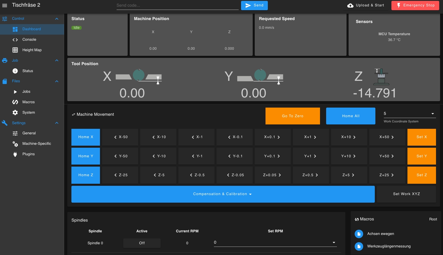
@droftarts Thank you for your support; it worked so far. However, after the tool length measurement, I have the problem that I can no longer move positively.
-
Home the machine; the machine position is all 0.
-
Tool length measurement.
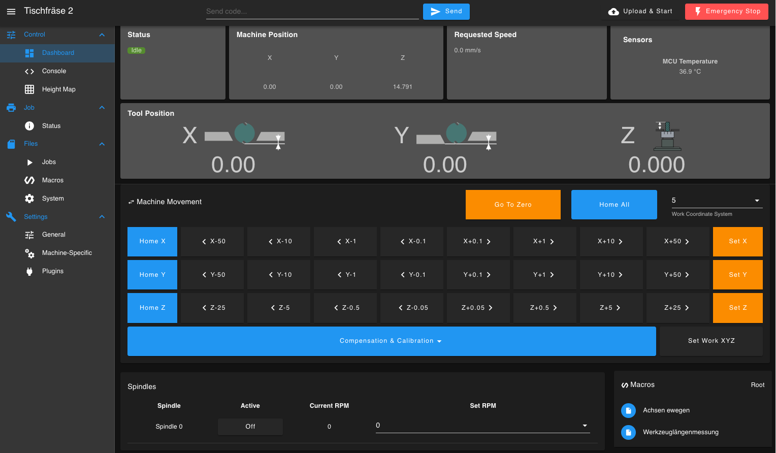
-
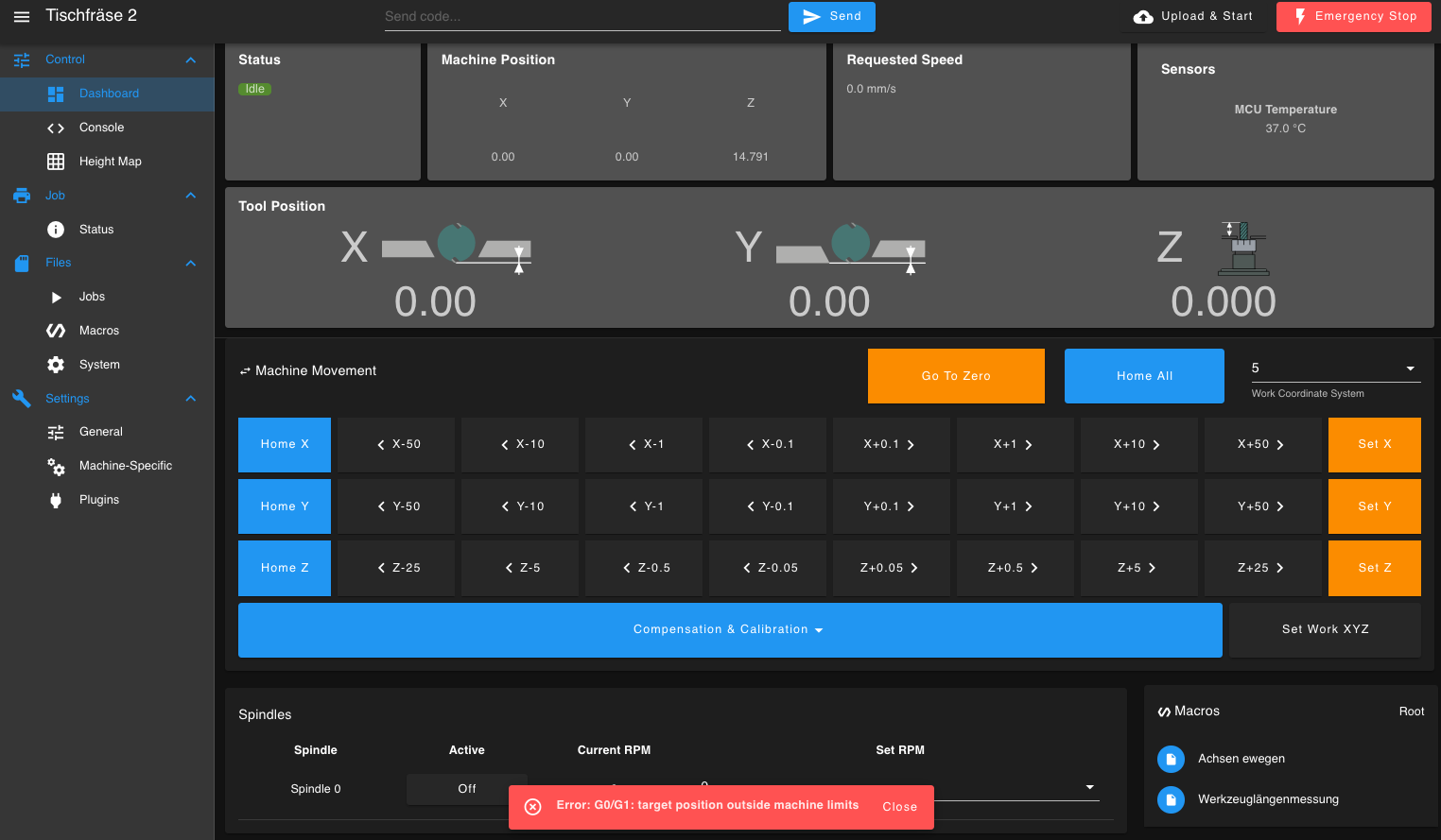
Now I can no longer move positively.
M291 P"Starte Werkzeuglängenmessung. Bitte sicherstellen, dass die Tastplatte positioniert ist." R"Werkzeuglängenmessung" S3
; Werkzeuglängenmessung auf Duet 2 WiFi

G53 G0 Z5              ; Fahre die Z-Achse in den Maschinenkoordinaten auf Z=5 (absolute Positionierung)
G91                    ; Schalte auf relative Positionierung
M574 Z2 S1 P"!e1stop"
G1 H1 Z50 F200          ; Fahre langsam nach oben (positive Richtung), bis der Schalterkontakt erreicht wird
G90                    ; Schalte auf absolute Positionierung zurück
M574 Z1 S1 P"!zstop"
M564 H4
M291 P"Messung abgeschlossen. Werkzeuglänge erfasst." R"Fertig" S1
; Configuration file for Duet WiFi (firmware version 3.3) ; executed by the firmware on start-up ; ; generated by RepRapFirmware Configuration Tool v3.3.14 on Sun Nov 20 2022 22:13:01 GMT+0100 (Mitteleuropäische Normalzeit) ; General preferences M453 G90 ; send absolute coordinates... M83 ; ...but relative extruder moves M550 P"Tischfräse 2" ; set printer name ; Network M552 S1 ; enable network M586 P0 S1 ; enable HTTP M586 P1 S0 ; disable FTP M586 P2 S0 ; disable Telnet ; Drives M569 P0 S0 ; physical drive 0 goes forwards M569 P1 S0 ; physical drive 1 goes forwards M569 P2 S0 ; physical drive 2 goes forwards M584 X0 Y1 Z2 ; set drive mapping M350 X16 Y16 Z16 I1 ; configure microstepping with interpolation M92 X1600.00 Y1600.00 Z1600.00 ; set steps per mm M566 X900.00 Y900.00 Z60.00 ; set maximum instantaneous speed changes (mm/min) M203 X3000.00 Y3000.00 Z800.00 ; set maximum speeds (mm/min) M201 X500.00 Y500.00 Z500.00 ; set accelerations (mm/s^2) M906 X2000 Y2000 Z2000 I30 ; set motor currents (mA) and motor idle factor in per cent M913 X100 Y100 Z100 ; Axis Limits M208 X0 Y0 Z0 S1 ; set axis minima M208 X75 Y75 Z120 S0 ; set axis maxima ; Endstops M574 X1 S1 P"!xstop" ; configure switch-type (e.g. microswitch) endstop for low end on X via pin xstop M574 Y1 S1 P"!ystop" ; configure switch-type (e.g. microswitch) endstop for low end on Y via pin ystop M574 Z1 S1 P"!zstop" ; configure Z-probe endstop for low end on Z M950 R0 C"e0heat+e1heat" Q100 L24000 M950 P1 C"e1heat" M563 P0 R0 S"Spindle" G10 P0 X0 Y0 Z0 G10 P1 R0 S0 M568 P0 F0 T0I have already tried all H(1-4), but it doesn’t provide a solution.
I want to take a break; maybe I will think of something later. -
-
I'm going in circles.
Point 1: What do I want?
I want to measure the length of the tool on my machine by moving the cutter upwards. However, the G30 command does not work for this.Point 2: Switch (contact method)
The switch is simply a metal plate that closes the circuit when the cutter touches it. This creates a connection between the milling table and the cutter.Point 3: Macro requirement
I need a macro that moves the Z-axis upwards and stops when contact (circuit closing) occurs. After contact, I want to zero the Z-axis in the work coordinate system. If necessary, I can do this manually.Point 4: Endstop issue
I tried solving this with endstops, but they don’t work well. After measuring the tool length, the travel path of the Z-axis shifts, and I can’t exactly describe the problem.Does anyone have an idea or an approach that could help me?
Thank you.
-
Can someone tell me in which area of the firmware the direction for tool length measurement is defined?
-
I did it. The solution was actually very simple, so I'm wondering why I didn't figure it out much earlier.
G38.3  Z  50  F  100
G10 L20 P1 Z0
https://youtu.be/7yjKVpkOM8k?si=Ropq6YF0fWoNj_r5
Thanks