Duet 2 and Duex 5 : BL Touch Wiring
-
@djthuma said in Duet 2 and Duex 5 : BL Touch Wiring:
M950 S0 C"duex.pwm1" ; Duet 2 WiFi/Ethernet + DueX2/5
Your config says DueX PWM1, that’s where you can plug in 5V, GND, and the control wire. The expansion connector, where pin exp.heater5 is, is where the DueX plugs in, so is not accessible.
Ian
Bed-slinger - Mini5+ WiFi/1LC | RRP Fisher v1 - D2 WiFi | Polargraph - D2 WiFi | TronXY X5S - 6HC/Roto | CNC router - 6HC | Tractus3D T1250 - D2 Eth
-
@infiniteloop
I was referring to this page on the documentation.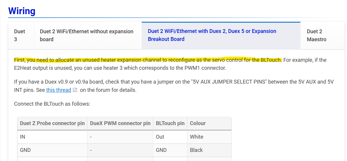
-
@droftarts Thank you.
When I plug in the Probe to PWM1 I get an over voltage error. The screen goes white. I unplug it, of course I don't want things to fry.
-
@djthuma said in Duet 2 and Duex 5 : BL Touch Wiring:
First, you need to allocate an unused heater expansion channel to reconfigure as the servo control for the BLTouch. For example, if the E2Heat output is unused, you can use heater 3 which corresponds to the PWM1 connector.
Yes, it's a bit confusing. Because each of the PWM and heater outputs are shared on the Duex, ie the same signal controls PWM1 as e2heat, and PWM2 is shared with e3heat, etc, you need to use a PWM connector whose matching heater is free. The naming of the heater outputs is also a little confusing; heater 0 is the bed heater, heater 1 is e0heat, heater 2 is e1heat, and the heater 3 pin on the expansion header (exp.heater3) controls e2heat and servo output PWM1 on the Duex!
I think I'll rewrite this in the morning, to make it clearer.
When I plug in the Probe to PWM1 I get an over voltage error. The screen goes white. I unplug it, of course I don't want things to fry.
That's not good. Most likely your wiring is incorrect, possibly you have shorted 5V to GND, or the servo control pin. Check your wiring. Post a picture if you're not sure.
Ian
Bed-slinger - Mini5+ WiFi/1LC | RRP Fisher v1 - D2 WiFi | Polargraph - D2 WiFi | TronXY X5S - 6HC/Roto | CNC router - 6HC | Tractus3D T1250 - D2 Eth
-
I was referring to this page on the documentation.
So we are on the same page

Can you share the version of your Duet board?
Do we talk about a genuine BLTouch or a lookalike (CR-Touch, BTT Microprobe, …)?
Which version is the BLTouch? -
@djthuma I've updated the text so it is clearer:
On the Duex and EBoB, connect the BLTouch GND, +5V, and control wires to an available three-pin PWM output. Connect the BLTouch out and GND wires to the Duet Z Probe connector.
On the Duex, heater outputs and PWM outputs share the same signal, ie the same signal controls PWM1 as e2heat, PWM2 is shared with e3heat, PWM3 is shared with e4heat, etc. You need to use a PWM connector whose matching heater is free.
I've also updated the wiring table, as it wasn't in the same order as the pins. Note that +5V is the middle pin on the PWM connector. See the wiring diagram: https://docs.duet3d.com/Duet3D_hardware/Duet_2_family/DueX2_and_DueX5#wiring-diagram
Ian
-
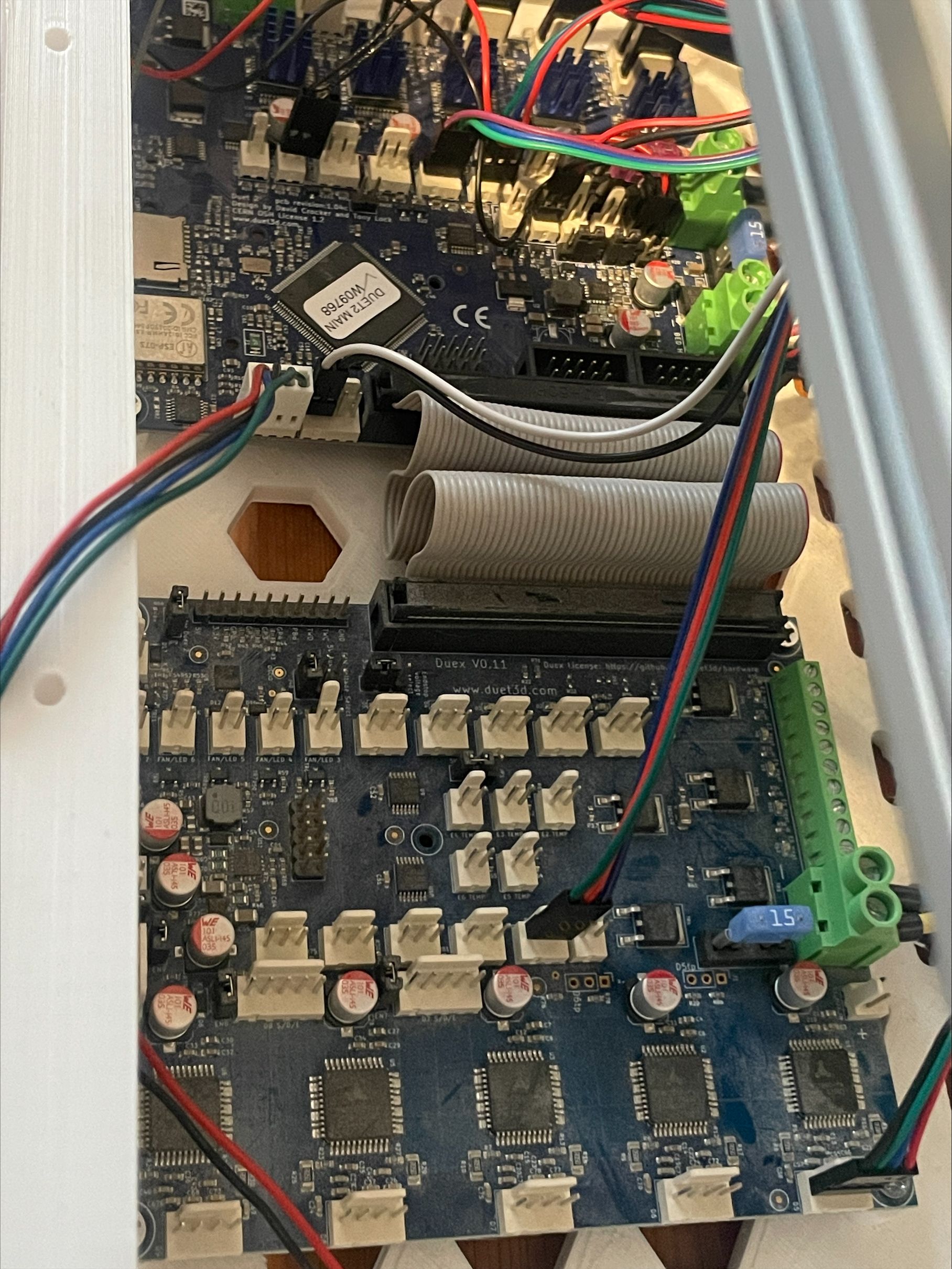
Attached a picture of the wiring of the board, when all plugged in and the BLTouch.
White = Z Probe in
Black = GND
Green = yellow = E2_PWM
RED = 5V AUX
Blue = GND
-
Config.g file
; Motor Idle Current Reduction
M906 I30 ; set motor current idle factor
M84 S30 ; set motor current idle timeout; Axes
M584 X0 Y1 Z2:5 ; set axis mapping
M350 X16 Y16 Z16 I1 ; configure microstepping with interpolation
M906 X800 Y800 Z800 ; set axis driver currents
M92 X80 Y80 Z400 ; configure steps per mm
M208 X0:200 Y0:200 Z0:200 ; set minimum and maximum axis limits
M566 X900 Y900 Z12 ; set maximum instantaneous speed changes (mm/min)
M203 X6000 Y6000 Z180 ; set maximum speeds (mm/min)
M201 X500 Y500 Z20 ; set accelerations (mm/s^2); Extruders
M584 E3 ; set extruder mapping
M350 E16 I1 ; configure microstepping with interpolation
M906 E1000 ; set extruder driver currents
M92 E420 ; configure steps per mm
M566 E120 ; set maximum instantaneous speed changes (mm/min)
M203 E3600 ; set maximum speeds (mm/min)
M201 E250 ; set accelerations (mm/s^2); Kinematics
M669 K1 ; configure CoreXY kinematics; Endstops
M574 X1 P"xstop" S1 ; configure X axis endstop
M574 Y1 P"ystop" S1 ; configure Y axis endstop
M574 Z1 S2 ; configure Z axis endstop; Probes
G31 P500 X0 Y0 Z0.7 ; set Z probe trigger value, offset and trigger height
M950 S0 C"duex.pwm1" ; Duet 2 WiFi/Ethernet + DueX2/5
M558 P9 C"^zprobe.in" H3 F120 T6000 ; configure BLTouch probe via slot #0
;M950 S0 C"zprobe.mod" ; create servo #0 for BLtouch; Mesh Bed Compensation
M557 X25:175 Y25:175 S40:40 ; define grid for mesh bed compensation; Sensors
M308 S0 P"bedtemp" Y"thermistor" A"Heated Bed" T100000 B4725 C7.06e-8 ; configure sensor #0
M308 S1 P"e0temp" Y"pt1000" A"Nozzle" ;T100000 B4725 C7.06e-8 ; configure sensor #1; Heaters
M950 H0 C"bedheat" T0 ; create heater #0
M143 H0 P0 T0 C0 S100 A0 ; configure heater monitor #0 for heater #0
M307 H0 R2.43 D5.5 E1.35 K0.56 B1 ; configure model of heater #0
M950 H1 C"e0heat" T1 ; create heater #1
M143 H1 P0 T1 C0 S285 A0 ; configure heater monitor #0 for heater #1
M307 H1 R2.43 D5.5 E1.35 K0.56 B0 ; configure model of heater #1
M950 H2 C"e1heat" T1 ; create heater #2
M143 H2 P0 T1 C0 S285 A0 ; configure heater monitor #0 for heater #2
M307 H2 R2.43 D5.5 E1.35 K0.56 B0 ; configure model of heater #2;M140 P9 H3 ; configure heater
; Heated beds
M140 P0 H0 ; configure heated bed #0; Fans
M950 F0 C"fan0" ; create fan #0
M106 P0 S0 L0 X1 B0.1 ; configure fan #0
M950 F1 C"fan1" ; create fan #1
M106 P1 S0 B0.1 H1 T45 ; configure fan #1
M950 F3 C"duex.fan3" Q500
M106 P3 S1 H-1; Tools
M563 P0 D0 H1:2 F0 ; create tool #0
M568 P0 R0 S0 ; set initial tool #0 active and standby temperatures to 0C; Miscellaneous
M501 ; load saved parameters from non-volatile memory -
What errors and or problems are you getting in this configuration?
Can you please send M122 and M98 P"config.g" and share the results?
-
@djthuma The colour of the wires at your BLTouch are reversed. See https://docs.duet3d.com/en/User_manual/Connecting_hardware/Z_probe_BLTouch#bltouch-pinout-and-wire-colours
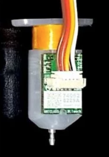
Normally brown and black are GND, but on yours its white and red. Assuming the plug isn't just plugged in backwards, the wiring from the BLTouch is:
GND +5V Control GND Out White Black Yellow > Green Red Blue Which explains why it's shorting out, as the red wire is connected to +5V on the PWM1 connector, and is shorting to the white wire, connected to Z probe in on the Duet.
Ian
Bed-slinger - Mini5+ WiFi/1LC | RRP Fisher v1 - D2 WiFi | Polargraph - D2 WiFi | TronXY X5S - 6HC/Roto | CNC router - 6HC | Tractus3D T1250 - D2 Eth
-
@droftarts Yes!
That did work to get the probe to function!
I just need to setup the z probe routine for bed leveling.I am running into a different error, trying to have multiple z axis motors.
Only one of them is functioning. Driver 2 with a jumper on the ZB segment.
Then trying to pair the driver 6 and 7 to the Z axis.Is this correct? When I jog after M564 H0, I only have one drive moving.
; Smart Drivers
M569 P0 S0 ;D1 ; driver 0 goes forwards (X axis)
M569 P1 S1 ;D2 ; driver 1 goes forwards (Y axis)
M569 P2 S1 ;D2 ; driver 2 goes forwards (Z axis)
M569 P3 S1 ;D2
M569 P6 S1 ;D2 ; driver 3 goes forwards (extruder 0)
M569 P7 S1 ;D2 ; driver 3 goes forwards (extruder 0); Motor Idle Current Reduction
M906 I30 ; set motor current idle factor
M84 S30 ; set motor current idle timeout; Axes
M584 X0 Y1 Z2:6:7; set axis mapping
M350 X16 Y16 Z16 I1 ; configure microstepping with interpolation
M906 X800 Y800 Z800 ; set axis driver currents
M92 X80 Y80 Z400 ; configure steps per mm
M208 X0:200 Y0:200 Z0:200 ; set minimum and maximum axis limits
M566 X900 Y900 Z12 ; set maximum instantaneous speed changes (mm/min)
M203 X6000 Y6000 Z180 ; set maximum speeds (mm/min)
M201 X500 Y500 Z20 ; set accelerations (mm/s^2)