IDEX BOTH ON CORE XY
-
@o_lampe Thanks and agreed - will be interesting to see some actual single print head test prints to see what I need to do in terms of retractions and zHopping etc. to get them to work. Printers currently out of action due to house guests - but hope to be able to get access again at the back end of the week.
-
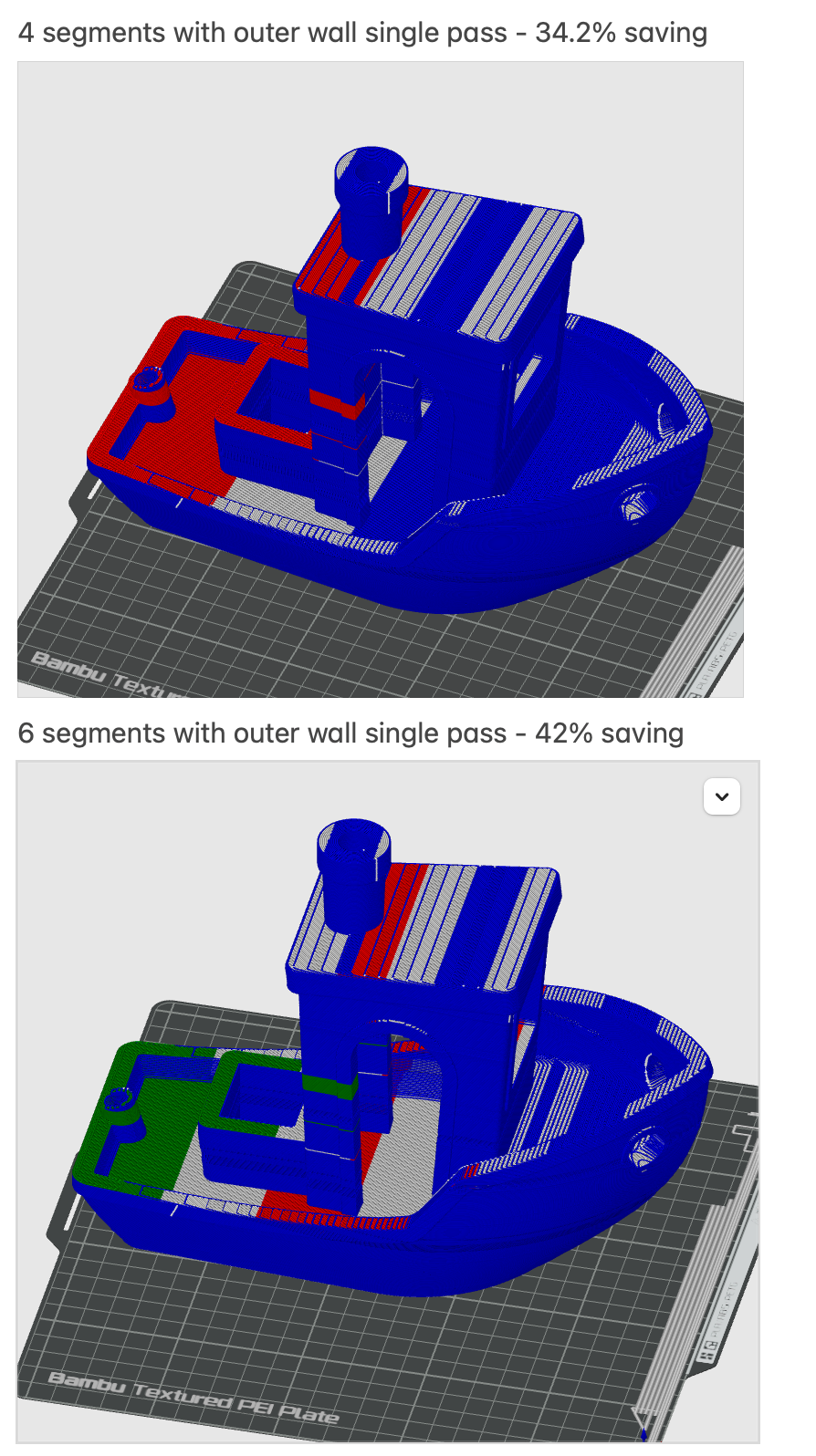
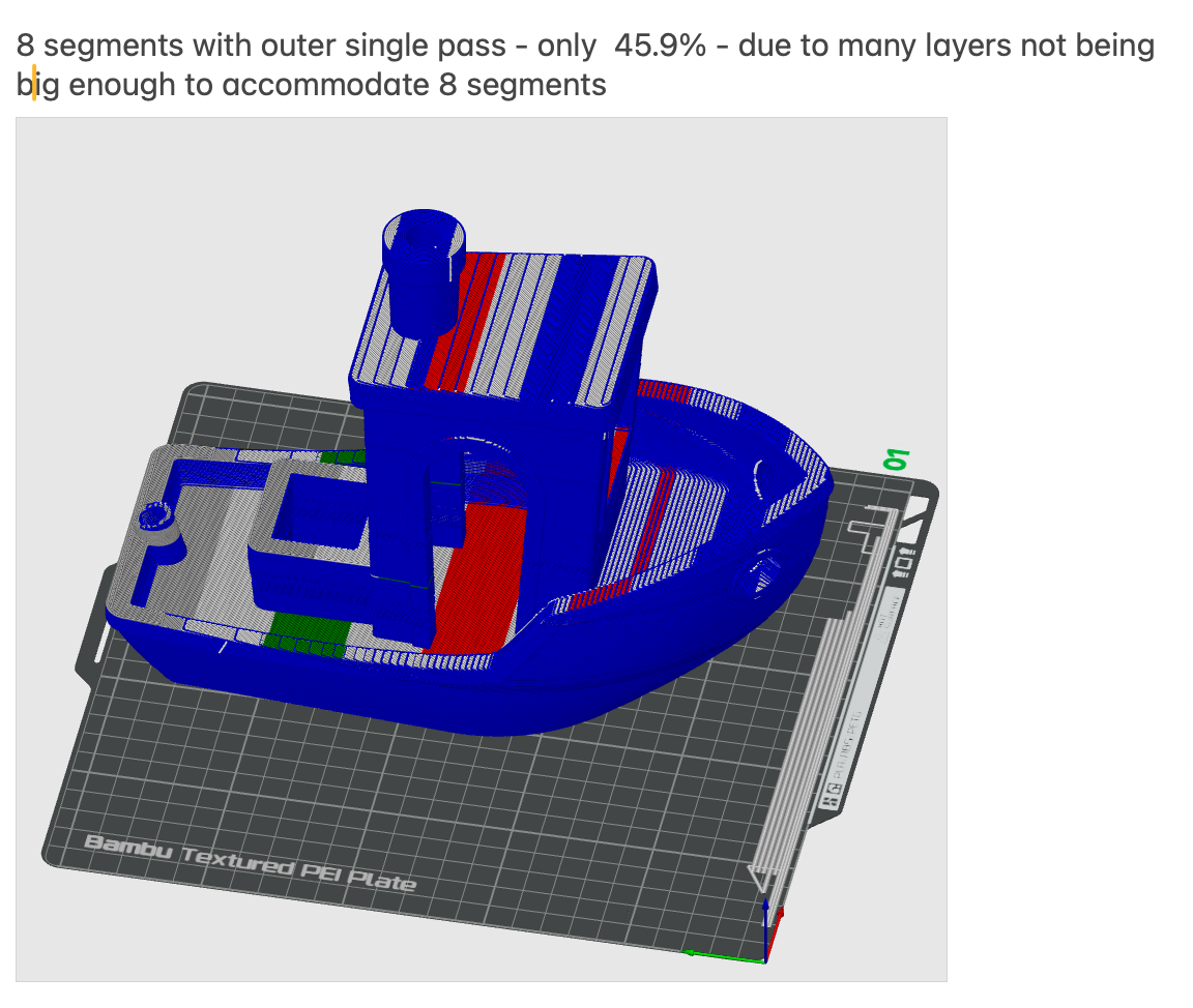
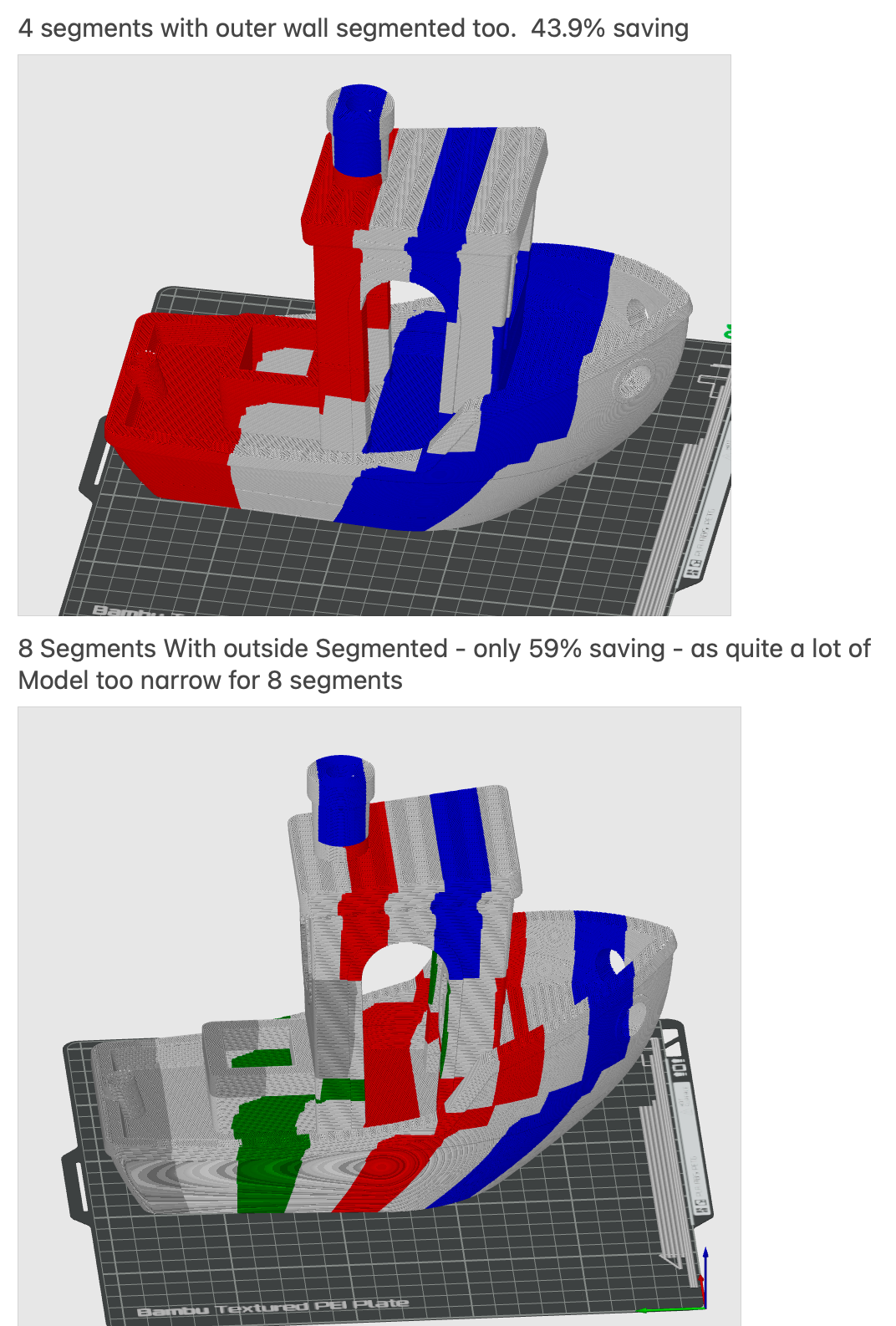
Have been working on some realistic timings to gauge the benefits on additional gantries.
Findings for the benchy model segmented into 4, 6 and 8 - for 2, 4 & 6 parallel gantries.
Doing outer walls in a single pass drops the percentage saving quite a bit (14-17% additional savings in these examples) - but I still think it is probably going to be worth doing for models that need to look good.
-
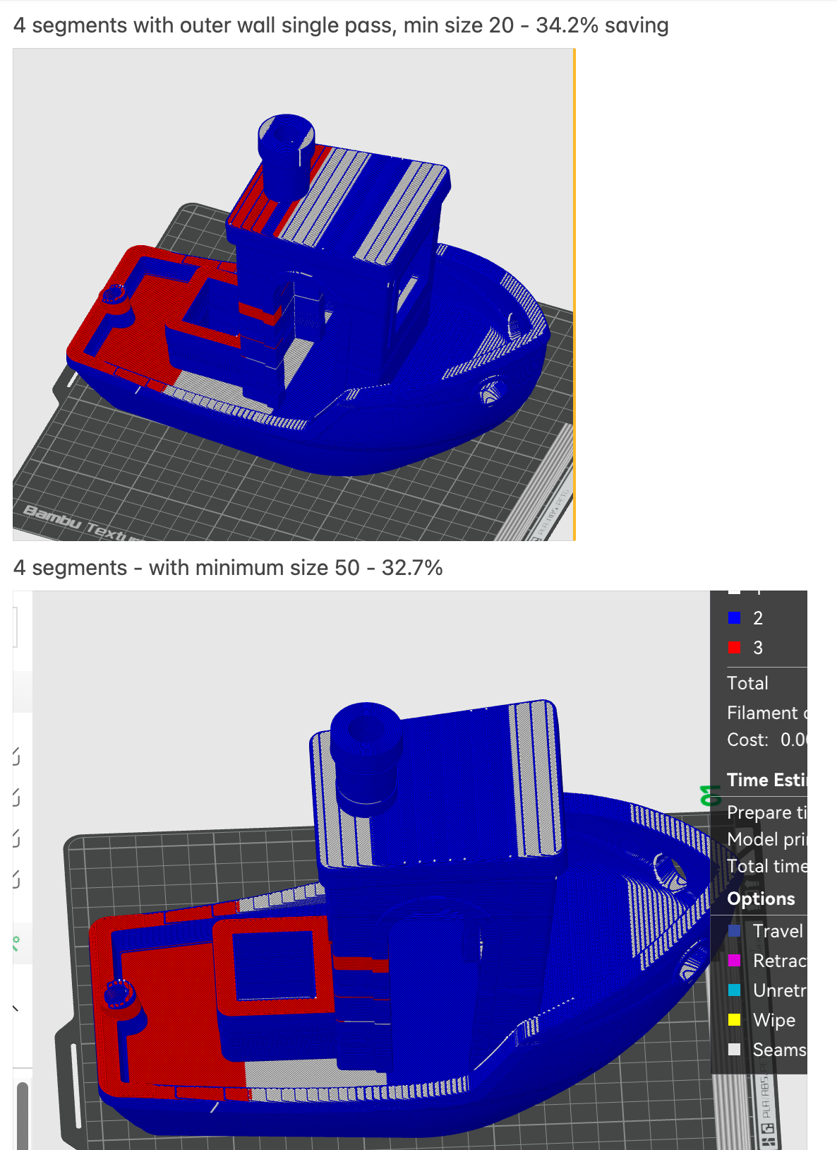
@dwuk I have a question regarding your segment width: From your last screenshot I guestimated in relation to your buildplate grid, that your minimal segment width is about 20mm. If I undestand correctly, you print every other segment simultaniously (like darker grey, green, red and blue) and then switch to the other half of the segments (the white ones) to ideally never have to park a gantry. My question would be, if those 20mm are a realistic assumption: If you have only two gantries, you can probably design a extruder, that has the nozzle axis quite close to one side (like the J1 Extruders but rotated), allowing you to put the nozzle axis planes of two gantrys about 20mm apart with additional hardware sticking out further to the front and the back. But if you have more then two gantries, the whole gantry width is relevant including aluminum profile, linear rail and carriage, motor, fan etc ... So, do I misunderstand something, are you using stand in values or is the buildplate texture differently scaled?
-
@JVan Well spotted - in the example the minimum segment depth is as you surmised only 20mm on a 256mm Y AXIS which isn't really practical for anything above 2 gantries (where you could rotate them around to get the print heads fairly close).
To go above 2 gantries using this approach the Y axis is going to need to be quite a lot large - 768mm for example would mean you could multiply the 20x3 - to get 60mm - which is still pretty small for current designs of extruders I know.
I think I should probably stick to a maximum of 3 gantries in later examples - maybe with unequal segment sizes to take in to account the centre gantry being rotated to face one of the others.
For 4 segments - pushing up the minimum size from 20 to a more practical 50mm doesn't lower the saving percentage too much - this equates to 100 on a 500mm print bed.
-
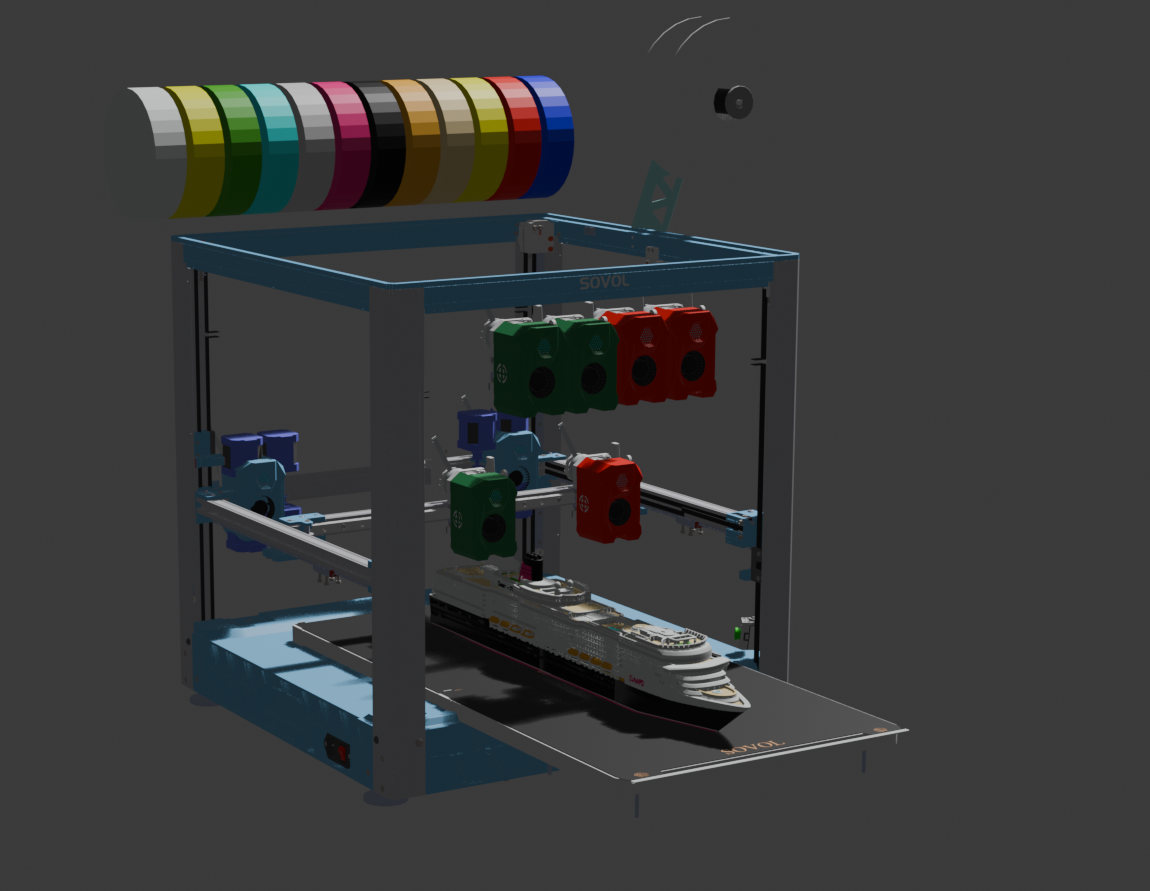
This might work as a suitable first test platform.
The print heads are quite big - about 100mm in total depth on a total 350mm build plate - but there is a fair bit of space at the back to allow the nozzle to get right to the back of the bed - so there should be scope to fit 4 reasonably sized segments on. It might be possible to reduce the depth by moving the fan and circuit board that take up a fair bit in front of the nozzle.
Quite a lot of extra weight on the flying Z gantry - with 6 extra XY motors, 3 extra print heads and an extra Y gantry -
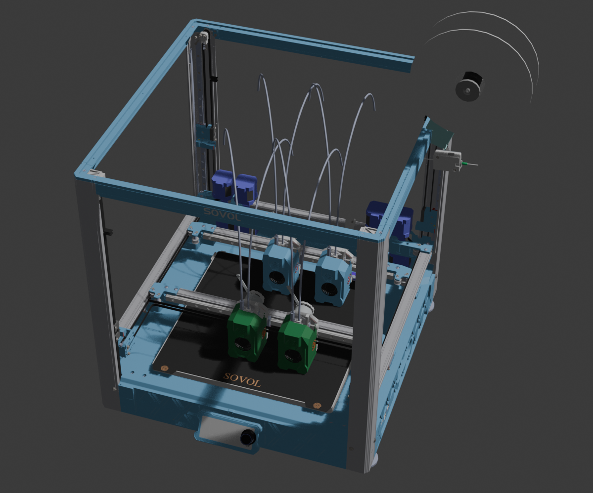
It might be feasible to expand the size in the Y direction - by moving the Z gantries back - ideally about 200-300mm, and extending the length the the Z gantry side parts and the top side frame.
-
@dwuk I'm concerned about the moving mass of the flying gantry. If I'd build such a printer from scratch, I'd choose a moving bed.
And I'd flip the front cross bar, so the green nozzles face the others
-
@o_lampe You might be right - I have been thinking about a Double Voron Tridex - but the price of the SV08 and the fact that it is mostly pre built is pretty attractive to me.
It might I guess even be possible to adapt it to have a moving bed instead of gantry.
I agree that swapping around the front heads would help with parallel printing - but then that would limit the ability to make the front heads tool changers - like @TeachingTech is trying to develop with the stealth changer people..
9 colours, 4 or which could be printed in parallel is getting close to the perfect printer for me...
Shame the SV08 print heads are so big.
-
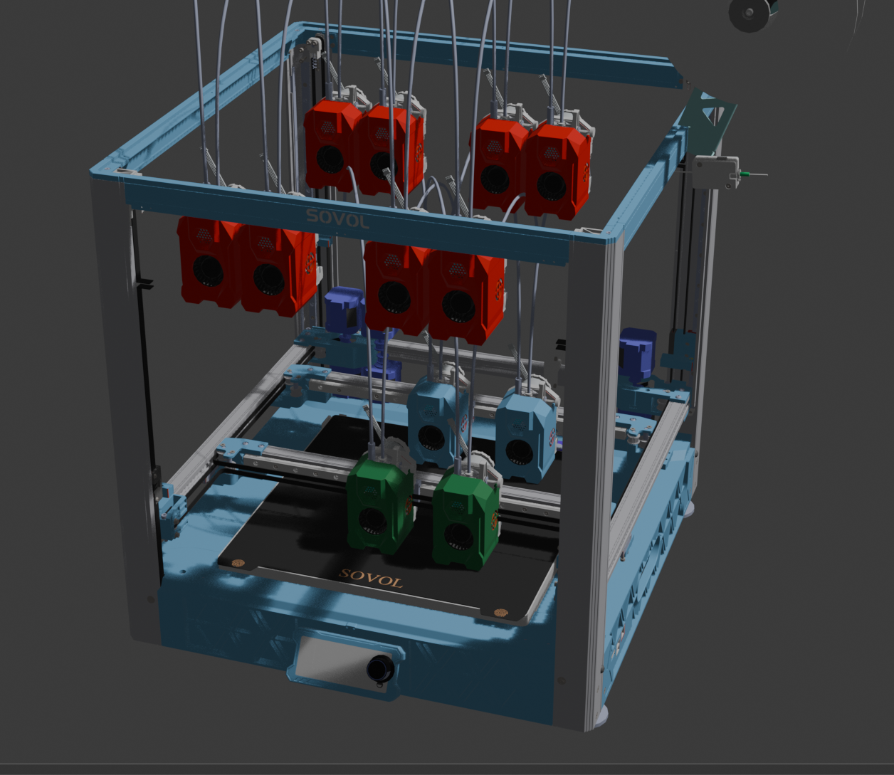
@dwuk With a toolchanger the frame is pretty cramped. Imagine you want to replace the left green tool with the right-most parked tool or the other way round....
-
@o_lampe I think you are right - didn't think about both print heads needing to tool change at the same time.
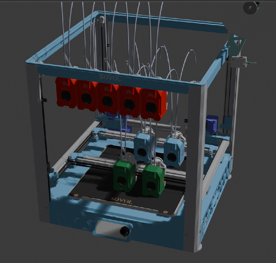
Have reduced the numbers of racked tools to 4 - but then added a second row for the back gantry to use. - Would obviously need hardware and holders.
I think I could as you suggested flip the whole front gantry and racked tools around - too - so that all of the racked tools are in the middle - however for the purposes of aesthetics I'll leave them facing all facing in the same direction for the simulations.
-
Tool changing harder to animate than some of the other concepts - initial basic animation created.
IDEX Part13 - Sovol SV08 IDEX Dual Gantry Tool Changer Concept - Youtube
-
@o_lampe After a fair bit of work to sort out the post processor - to make sure it doesn't miss out any important not G0/G1 commands, first test print completed on single headed printer.
I need to do some work on feed rates and travel move speeds as I think they are getting messed up - but the actual first few layers of the
 print worked.
This was print with the outer wall single threaded, with the bottom surface done in 4 chunks - 2,0,3,1
-
@dwuk
@o_lampe Prints now working quite well - have attached link to a video containing two full prints.
-
@dwuk Seems to work already!

But around 32:00 I saw a potential improvement. Your post processor seems to print some tracks "from the far end" which adds unnessesary travel moves. A small routine that checks for shortest travel move would help here.
Other than that, I think the result will look even better with two tools. It would avoid oozing during travel moves.
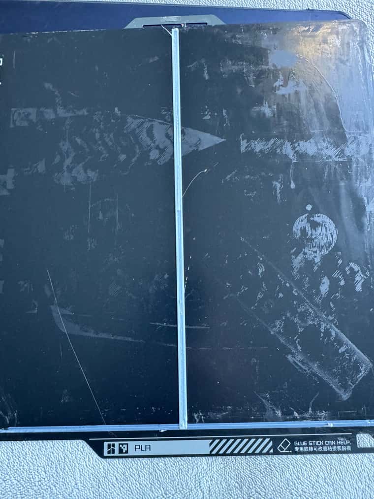
Maybe add the option to do the top infill layer in one go?A bit of concern is the mesh-bed compensation: That printer seems to be aligned badly. Just for fun you could try to print without mesh leveling. It'll give you a good taste of things to come with 2+2 tools. (not being able to use mesh levelling was the major reason I disassembled my hashPrinter)
-
@o_lampe Thanks - agree that there is a lot of room for optimisation of travel moves etc. as you suggest.
I haven't even implemented any additional z hopping or retractions for long moves yet either - which should further improve the results.
Will add in option for top surface to be single threaded - and possibly bottom too - although it is hard to notice the gaps on the bottom.
Will look into the mesh levelling. I usually only enable bed levelling very occasionally - and didn't for those test prints - so will do a rerun with levelling on.
Will see if it makes a difference when I do the next tests.
Will also do side by side tests with portioned and non partitioned prints too - Maybe in a colour where it is easier to see the detail.
Re mesh levelling for 2/4 tools - I would like to find a way for auto levelling and alignment to work - especially once I have given the ability for each of the heads to be independently lifted for Z hopping etc.
-
Probably an idea too far -
Would really like to print the occasional object around 600m long - but don't really want a massive printer - so a 350mm bed probably a good compromise..
Did think about extending the whole frame - but had another idea - occasional moving bed - most printing would be done with the CoreXY 350x350 non moving bed (with up to 4 print heads in parallel) - but up to three times a layer the whole bed could be moved back or forward in 115mm steps.
This could combine quite nicely with the parallel printing capability - as 6 x 115mm segments would cover the whole double bed length - and would mean there is no risk of head clashes.
Could potentially combine quite nicely with some sort of auto eject system too if the two build plates were kept separate.
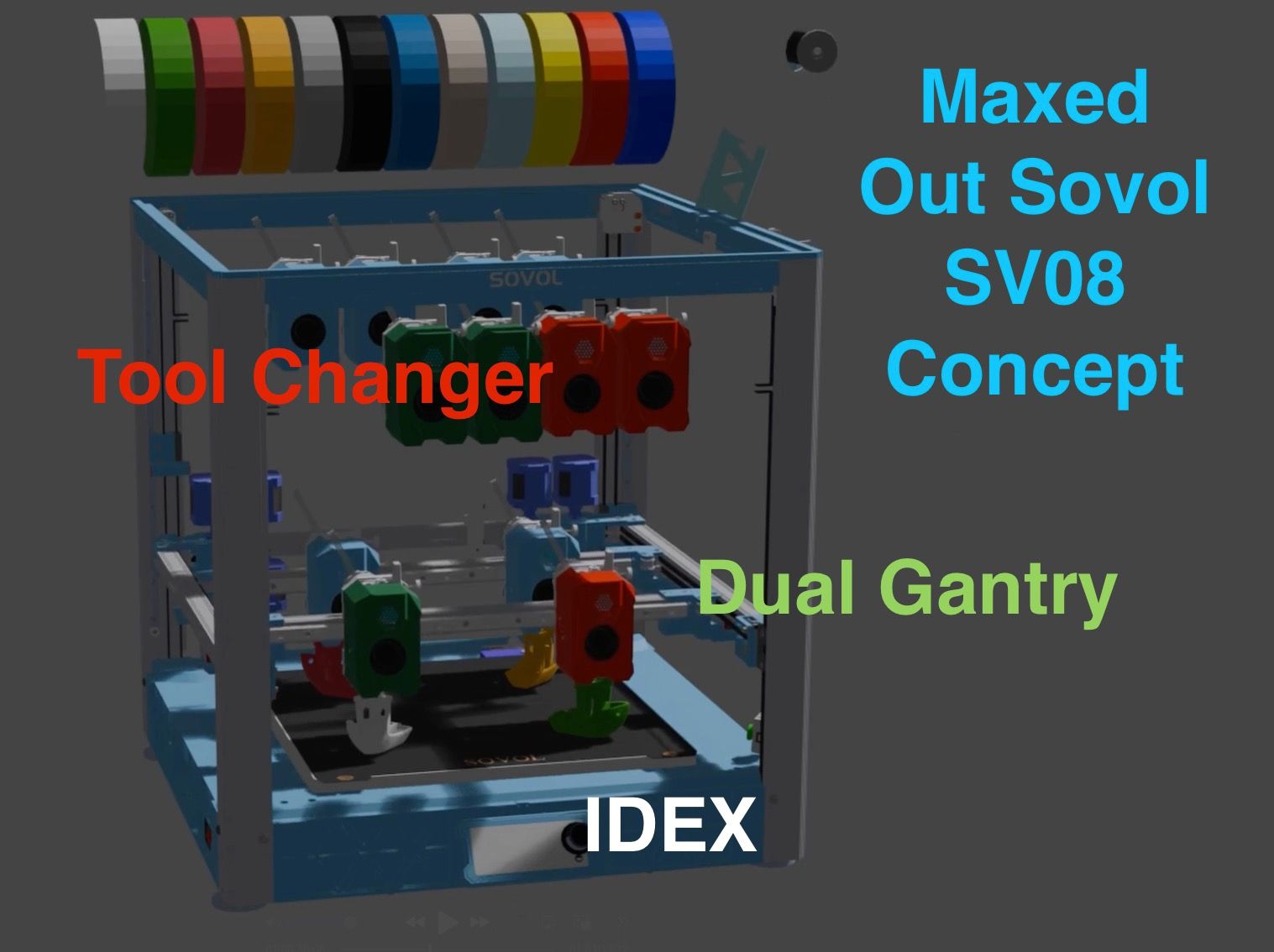
The whole system will likely then have 3 levels of colour change:
- Fast change for 2-4 colours - using double gantry IDEX
- Efficient change - using 4 more tool changer heads - possibly with different nozzle sizes too.
- tool changer could also be used to offload one of the front IDEX heads - for really fast single head printing.
- Slow change - using a AMS/MMY multiplexer with 16+ less frequently used colours
-
@dwuk said in IDEX BOTH ON CORE XY:
I usually only enable bed levelling very occasionally - and didn't for those test prints
The camera gave a different impression? I could clearly see the edge of the bed moving up/down. But maybe it's the cameramount moving....
-
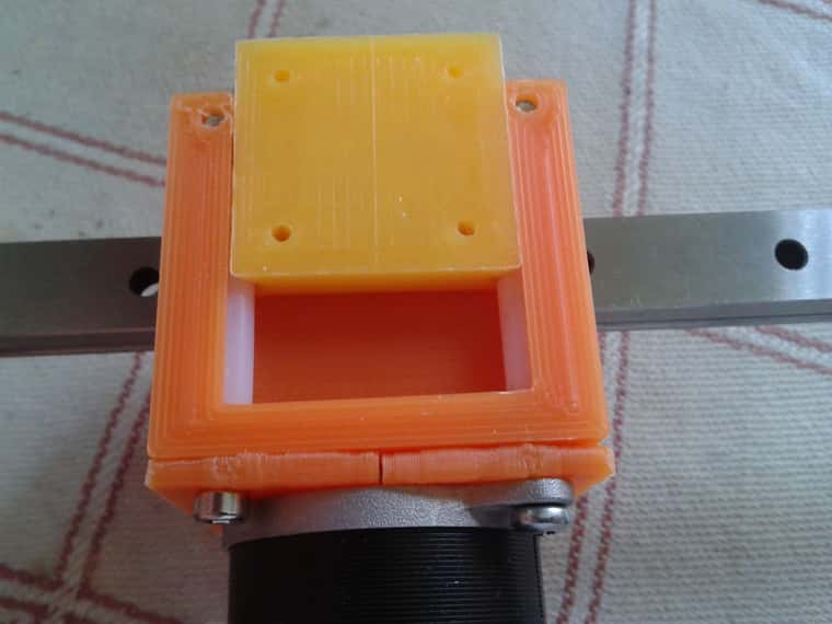
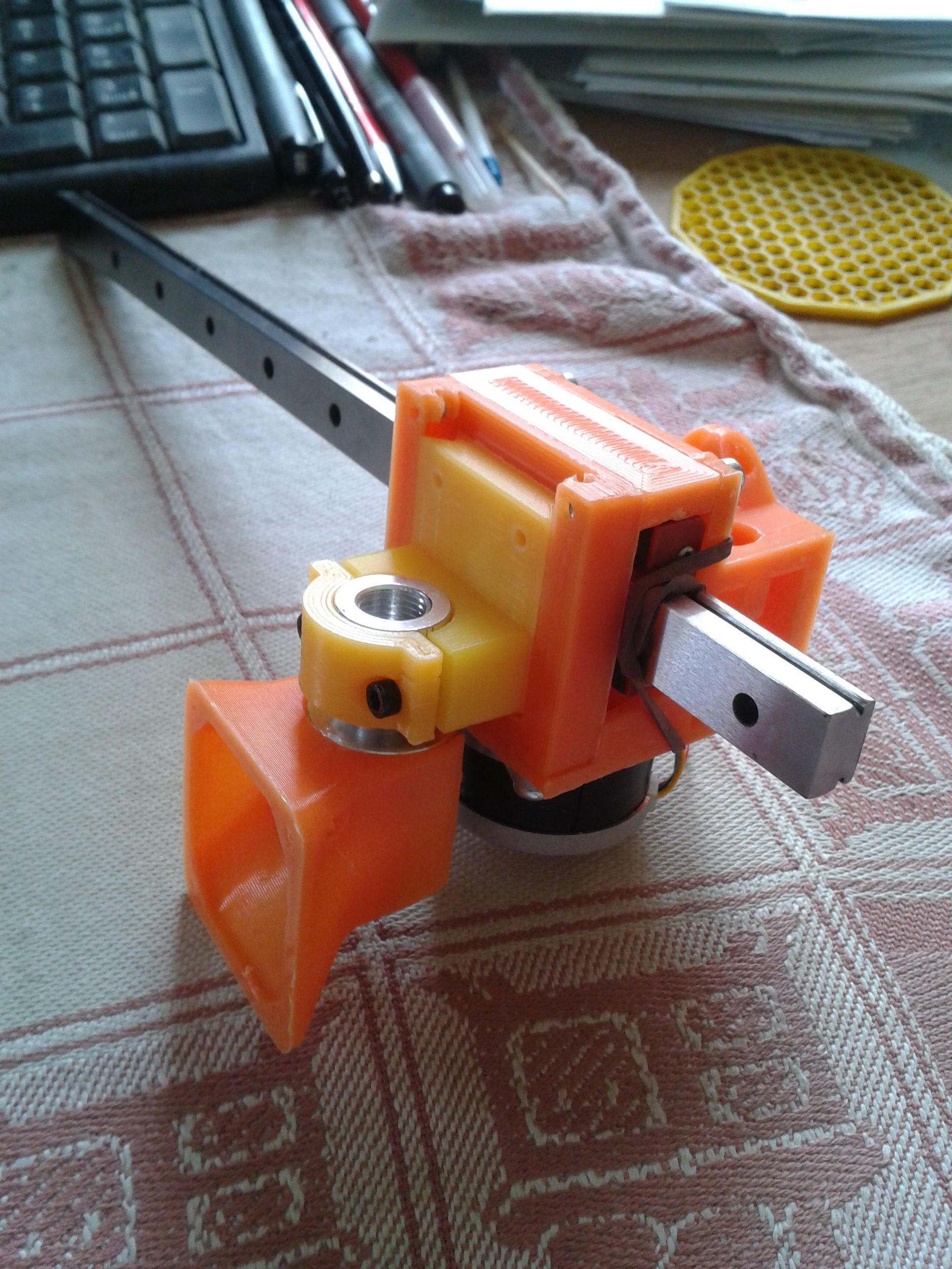
@dwuk Regarding Z-hop: I made a dovetail(ish) hotend mount for a different project and it was meant to adjust z-height for each toolhead individually. A motorized version with a small geared N20 motor was in the making, but the FW didn't have means to poll the heightmap for dual head printing (2021). Also driving dc motors with encoder was experimental, now it would be much easier with the step/dir interface of simpleFOC.
-
@o_lampe Interesting. When I say I don't run bed levelling - I mean't I don't enable the re-mesh - (where it goes and does lots of bed probing every time).
I think in that case what the Bambu Lab printers do is just a small number of taps to check that the mesh seems roughly the same. If it is they just use the stored mesh.
If the taps show a big difference then I think they do then re-mesh anyway.
It might be possible I guess to completely turn off the use of a mesh - via changing the start gcode.
-
@dwuk There are two different methods:
G32 = calibrating the bed tilt, by probing next to the leadscrews
G29 = using a probing grid or continuous probing to create a mesh -
@o_lampe Interesting - will have to do something like that.
I got the idea to enable Z Hopping and therefore the ability to more independently print on the second gantry from @8MEKAN8 commenting on this video
https://youtu.be/WbJ0lNdXzsI?si=LUPyYutux6sHN9HcIt looks like the Voron Tap might be a possible solution - although it might not be accurate enough to take into account mesh adjustments if it just uses a servo.
The other idea I had was to completely double up the flying Z gantry - with one on top of the other - with its own 4x Z axis motors - with the extruders on the top gantry being longer - so that they can fit through.
In the first instance I am going to try adding a 2nd gantry to the basic printer - probably without any Z hopping - so it will only be able to mirror or duplicate the first gantry - and just try out how much the extra weight affects performance and speed.
Then if it works ok will add the Z hopping to one of the extruders - so that I can try some parallel printing.