Inductive probe voltage too low for 1LC tool board
-
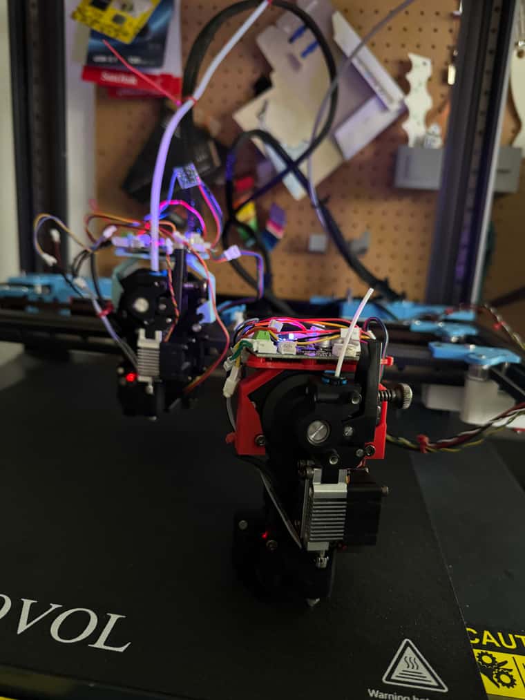
I am trying to connect a sovol SV08 24v inductive problem to a 1LC tool board.
The output from the probe is normally close to 0V, but when the probe is near the print bed the output goes to about 2.2V.
I am connecting it to IO0.in , VIN (from Power In) and GND from IO 0.
The trigger voltage does not seem to be enough to trigger the probe detection.
I have tried pull up resistors but that doesn't seem to work.
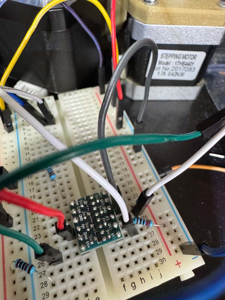
I thought I would try a logic shifter - so I have wired this up as follows
HV - 5V (from IO0), GND from IO0, LV - between Two 2K2 resistors - one from GND and one from 5V - to give me about 2.5V.
Now with the sensor connected to LV1 and IO0.in connected to HV1 It seems to work - and get either 0 or 1000 (in red) showing on the Duet Web interface.
Is there a better solution than this to get this probe to work from a 1LC tool board?

-
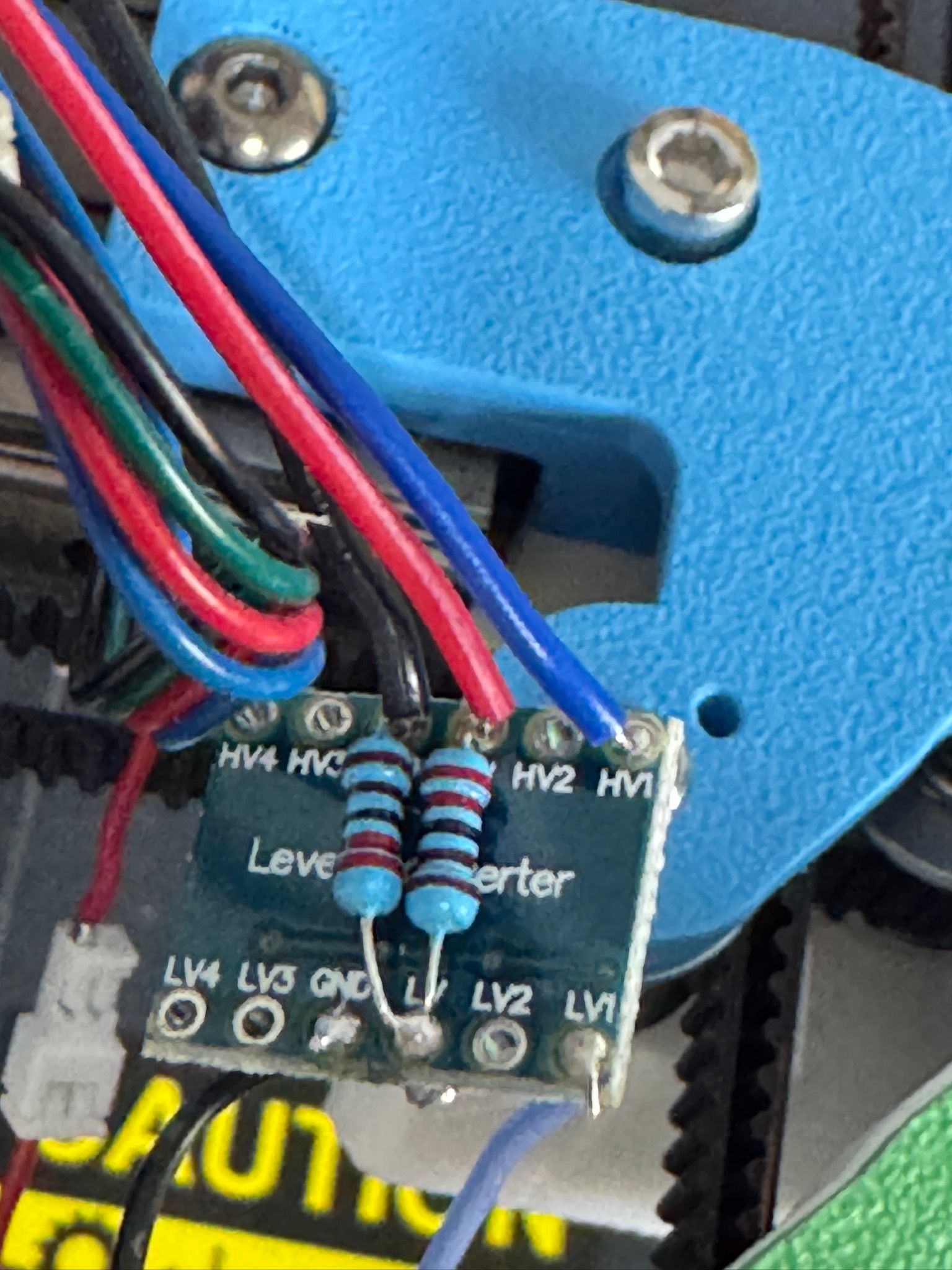
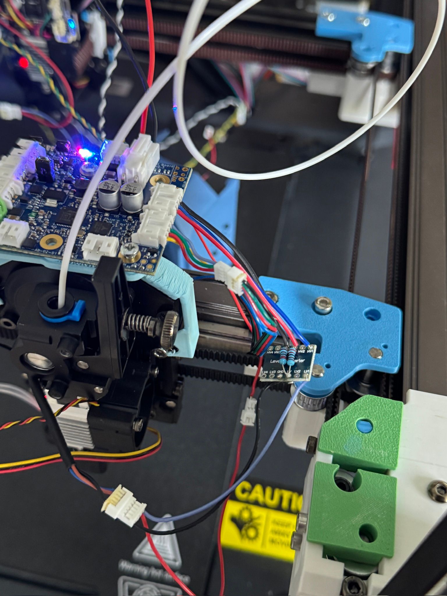
Soldered up version.
-
@dwuk I don't think you need the level shifter. If the probe is running on 24V, I think the output is 24V (though may be 5V). On the 1LC,
io0.in,io2.inandio3.inare all 30V tolerant.io1.inis the only one that is only 3.3V tolerant. See https://docs.duet3d.com/Duet3D_hardware/Duet_3_family/Duet_3_Toolboard_1LC#pin-namesIan
Bed-slinger - Mini5+ WiFi/1LC | RRP Fisher v1 - D2 WiFi | Polargraph - D2 WiFi | TronXY X5S - 6HC/Roto | CNC router - 6HC | Tractus3D T1250 - D2 Eth
-
I would have expected it to be 24v too - but it didn't work - so I checked on both the Duet connected extruder and also the other extruder that is still Klipper connected at the moment:
It is 0.0045 when not activated

And 2.223 when activated - which leaves the sensor at 0.

-
@dwuk is that probe a standard NPN or PNP output sensor; if so, which?
Duet WiFi hardware designer and firmware engineer
Please do not ask me for Duet support via PM or email, use the forum
http://www.escher3d.com, https://miscsolutions.wordpress.com -
@dc42 NPN according to this
https://www.sovol3d.com/products/proximity-sensor-switch-for-sv08?srsltid=AfmBOopCtLxcjr8lgDNf6jKj4S3MjcvtNUY8LsOw4IMveEWSM-GJRphGI tried the pnp suggested resistors in the documentation and that didn't seem to work.
-
@dwuk if it's definitely NPN then connect the output of the sensor directly to the IO_IN pin. See https://docs.duet3d.com/User_manual/Connecting_hardware/Z_probe_connecting#npn-output-normally-open-inductive-or-capacitive-sensor.
Duet WiFi hardware designer and firmware engineer
Please do not ask me for Duet support via PM or email, use the forum
http://www.escher3d.com, https://miscsolutions.wordpress.com -
@dc42 yes thats what I am doing - but the 2.2v closed voltage isn't triggering the Z Probe. If I logic shift it up to near to 5v on the IO0.ini pin it triggers
-
@dwuk instead of a level shifter try adding a pullup resistor between the sensor output and +5V on the IO connector. I suggest a value of between 1K and 10K.
Duet WiFi hardware designer and firmware engineer
Please do not ask me for Duet support via PM or email, use the forum
http://www.escher3d.com, https://miscsolutions.wordpress.com -
@dc42 Thanks - I tried it with a 2k2 I think and it made hardly any difference to the voltage - but will try again with a 1K
-
@dwuk it's odd that it's producing such a low output voltage. What supply voltage are you giving it?
Another option may be to connect a small signal silicon diode (e.g. 1N4148) between the output and the pullup resistor (diode cathode to the sensor output0 and connect the junction of the diose and resistor to the Duet input. That will shift the voltage level up by about 0.6V.
Using IO3.in instead of IO1.in may also help, because IO3.in accepts lower logic levels than IO1.in.
Duet WiFi hardware designer and firmware engineer
Please do not ask me for Duet support via PM or email, use the forum
http://www.escher3d.com, https://miscsolutions.wordpress.com -
Thanks for your help.
Yes definitely 24v supply voltage (which was a bit tricky to achieve on the 1LC board - is there a better way than tapping the input wire?). - have tested it on both the 1LC connected extruder and the other extruder still connected to the existing SV08 board - and they are both 24v supply and 2.2v signal when activated.
I will order some diodes and do a test when they arrive.
Just to confirm I am using the Z Probe input IO0.in - I thought IO1.in was for filament monitors - is that an option? - and does that have a lower signal detection level than IO0.in - being that it is only 3.3v tolerant. I can't find where it is documented what the signal switch level is for any of the 1LC io.in pins.
Will try both IO1.in and IO3.in next - both with just the 2.2v signal feed to see if either of those work.
-
@dc42 good news - Wired up my 2nd extruder - and this time I connected the Inductive Z probe ( 24V, 2.27V output) to the Filament Monitor 3.3v compliant connection IO1.in - and it seems to trigger ok.
So I think that is the solution unless I decide to add filament monitors. So thanks for your help.
Next issue is work out is how to handle 4 different Inductive Probes, a Switch Type Touch probe plus a positioning probe.