Support for AS5311 High Resolution Linear Encoder
-
@dc42 I decided not to use the Linear encoder for the time being. I will install end stops. Thanks for the answers.
HHmm. Maybee the linear encoders are only used as end stops.
Question: Can I use the PWM signal from the AR5311 as end-stop signals in RRF?
-
@Guus The processing board and the driver board where not that complex. I don't see it being used with closed-loop steppers.
-
@Guus These are the steppers.
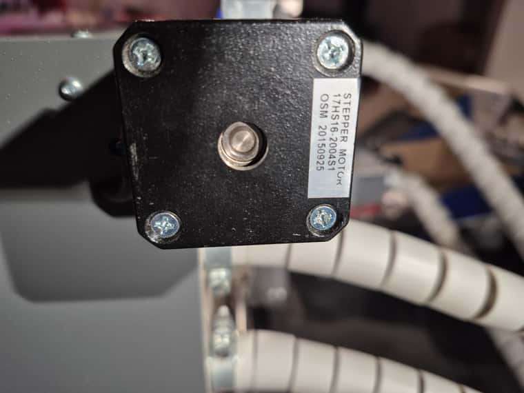 atv the X axis.
 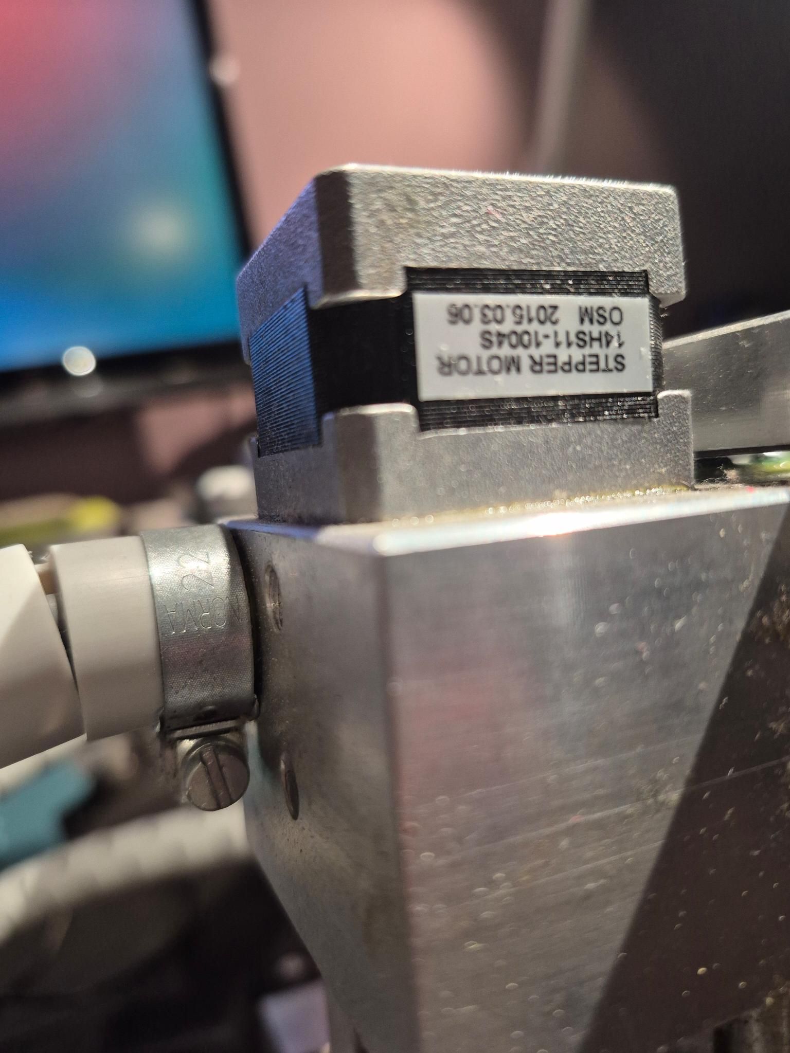 at the two Y steppers and
 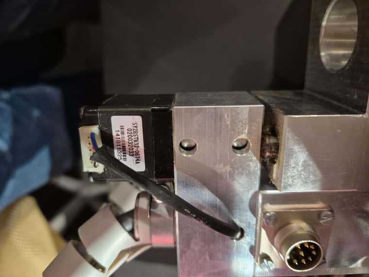 at the Z stepper.
 -
@Guus said in Support for AS5311 High Resolution Linear Encoder:
Can I use the PWM signal from the AR5311 as end-stop signals in RRF?
No, but those encoder have an Index output, if that index pulse is at the right point on the axis it might be possible to use that.See DC42's response below. -
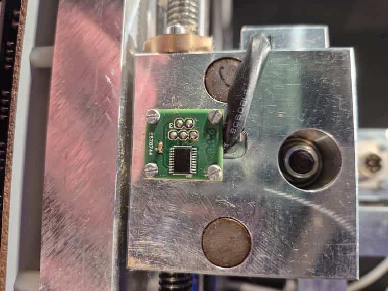
@Guus the index pulse is generated once every pole pair (see page 10 of the datasheet), so it's not much use as an endstop. I guess you could use it to detect the passing of a magnet, but a Hall effect device would do that more simply.
-
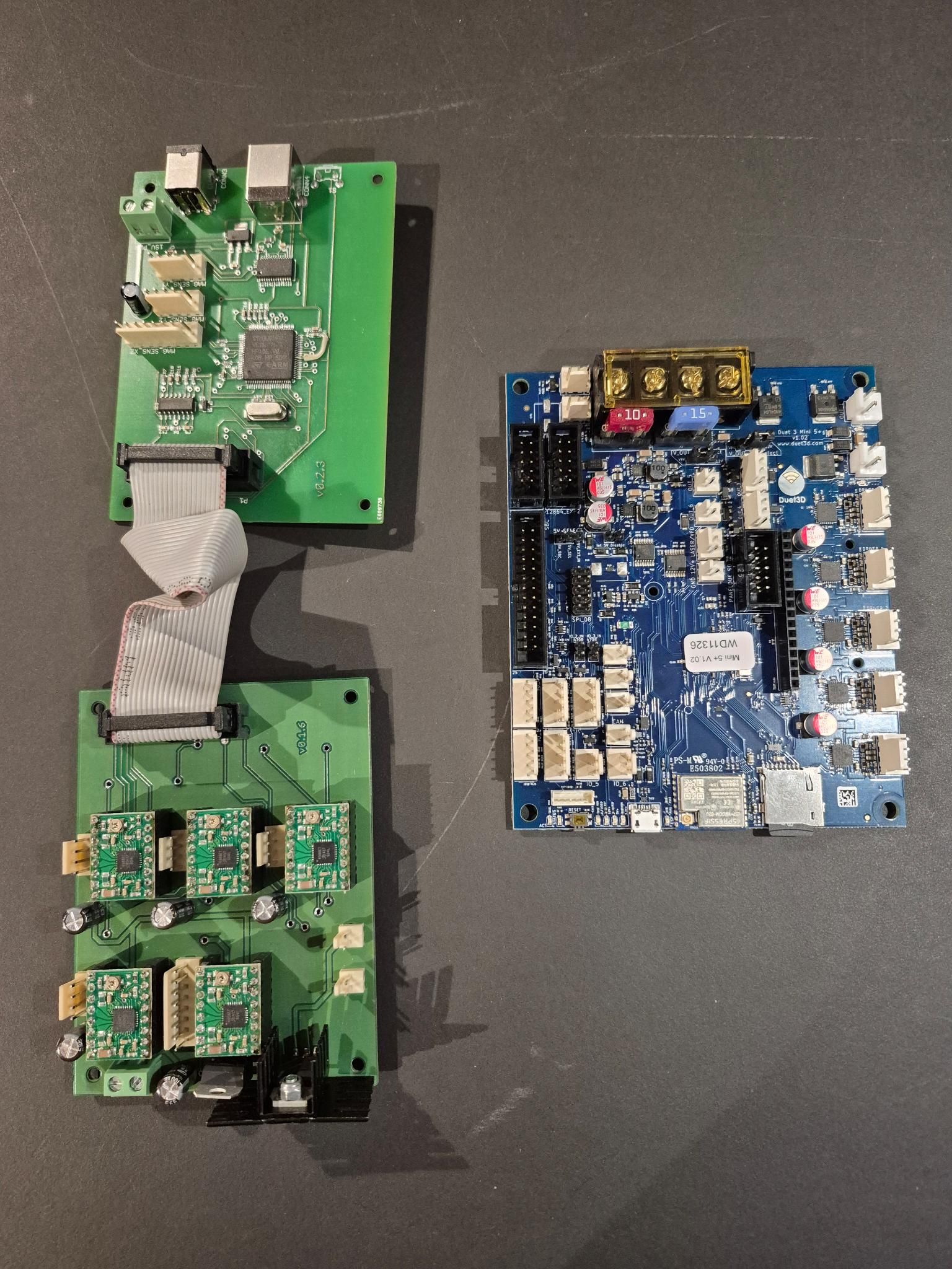
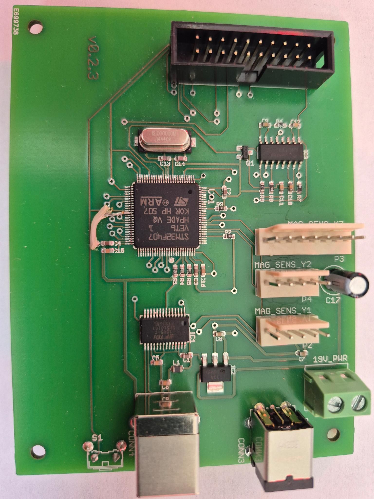
@Guus The controller board is interesting. It looks like it has an ARM MCU, and the encoder plugs in directly to that. The stepper drivers are standard 'stepstick' plug-in modules, and are probably Allegro A4988 drivers. I'd guess the firmware reads the motor position from the encoder, and maybe adjusts the position, but this isn't quite closed loop, as it's not taking the motor commutation into account, which allows for accurate positioning. The drivers on the Mini 5+, even though in open loop mode, will be nicer!
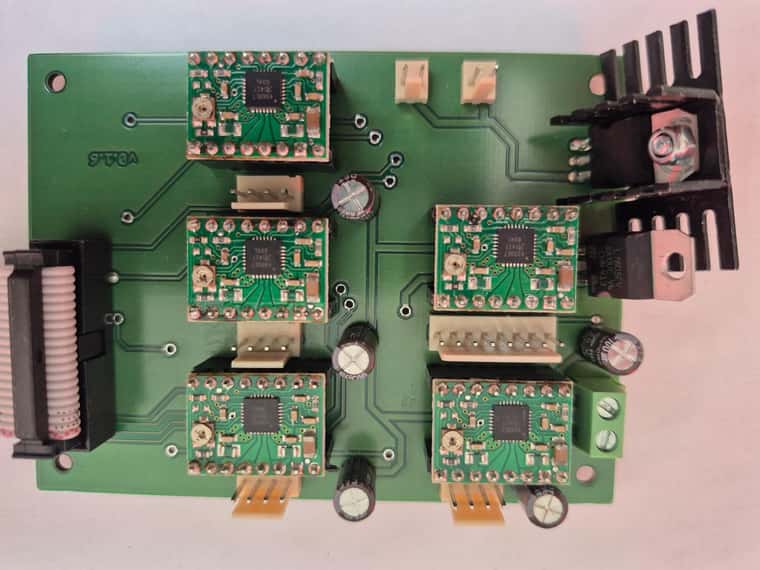
Interesting that there are 5 drivers on the motor board. I guess it uses three for X, Y and Z. Does it use the driver with 8 output pins for Y? What does it use the other drivers for? I did see it comes with other tools, eg paste dispenser and pick-and-place toolhead, so I assume those.
Ian
Bed-slinger - Mini5+ WiFi/1LC | RRP Fisher v1 - D2 WiFi | Polargraph - D2 WiFi | TronXY X5S - 6HC/Roto | CNC router - 6HC | Tractus3D T1250 - D2 Eth
-
Here are more photo's. This will explain many questions very fast.
The boards;
MCU board front side
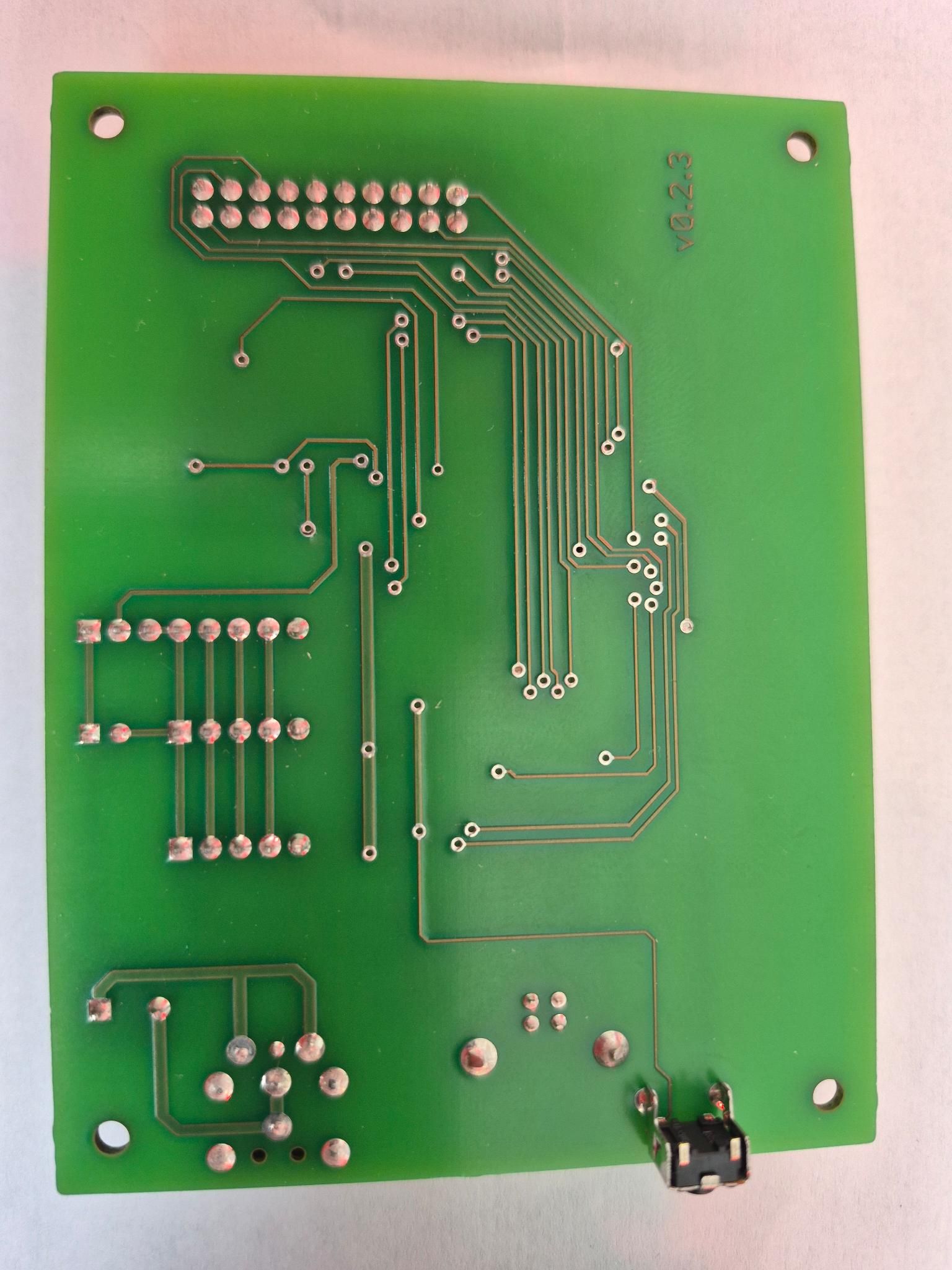
MCU board rear side
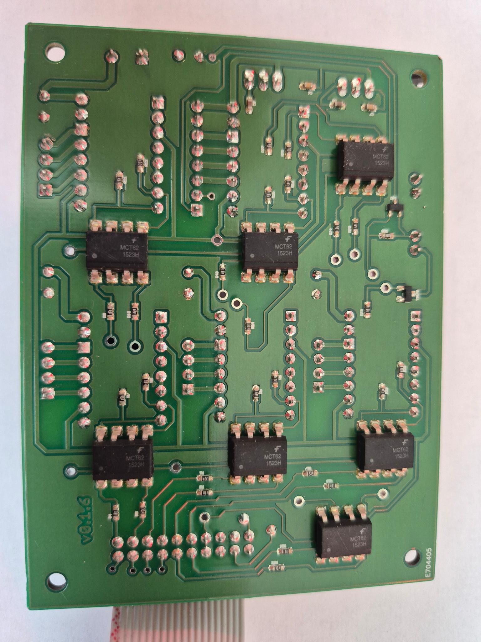
Driver board front side with ET4988 chips.
Driver board rear
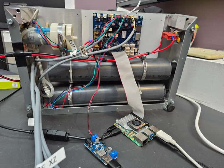
Bottom with Duet Mini 5. You can see 2 tubes with compressed air and a vacuum pump.
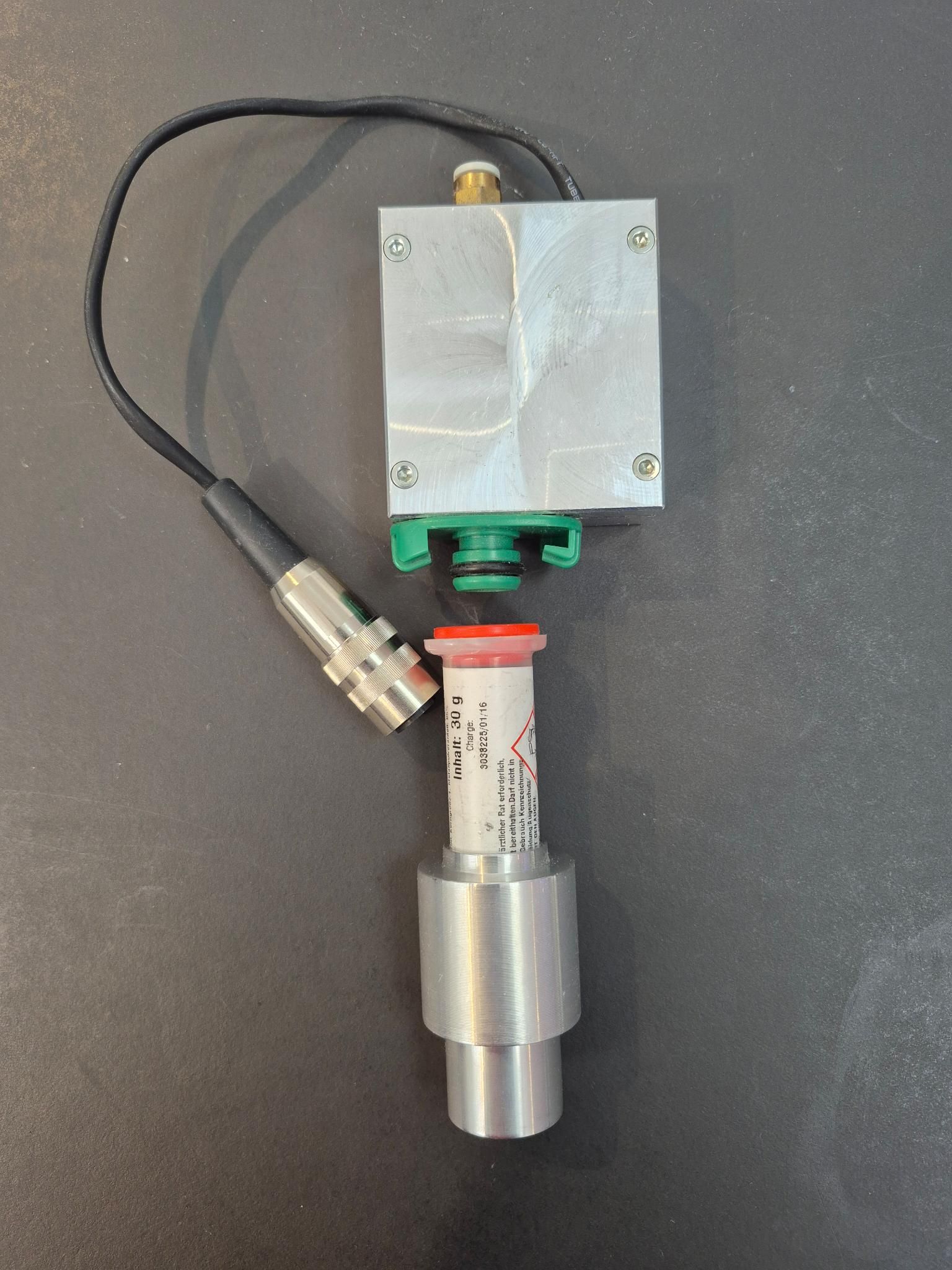
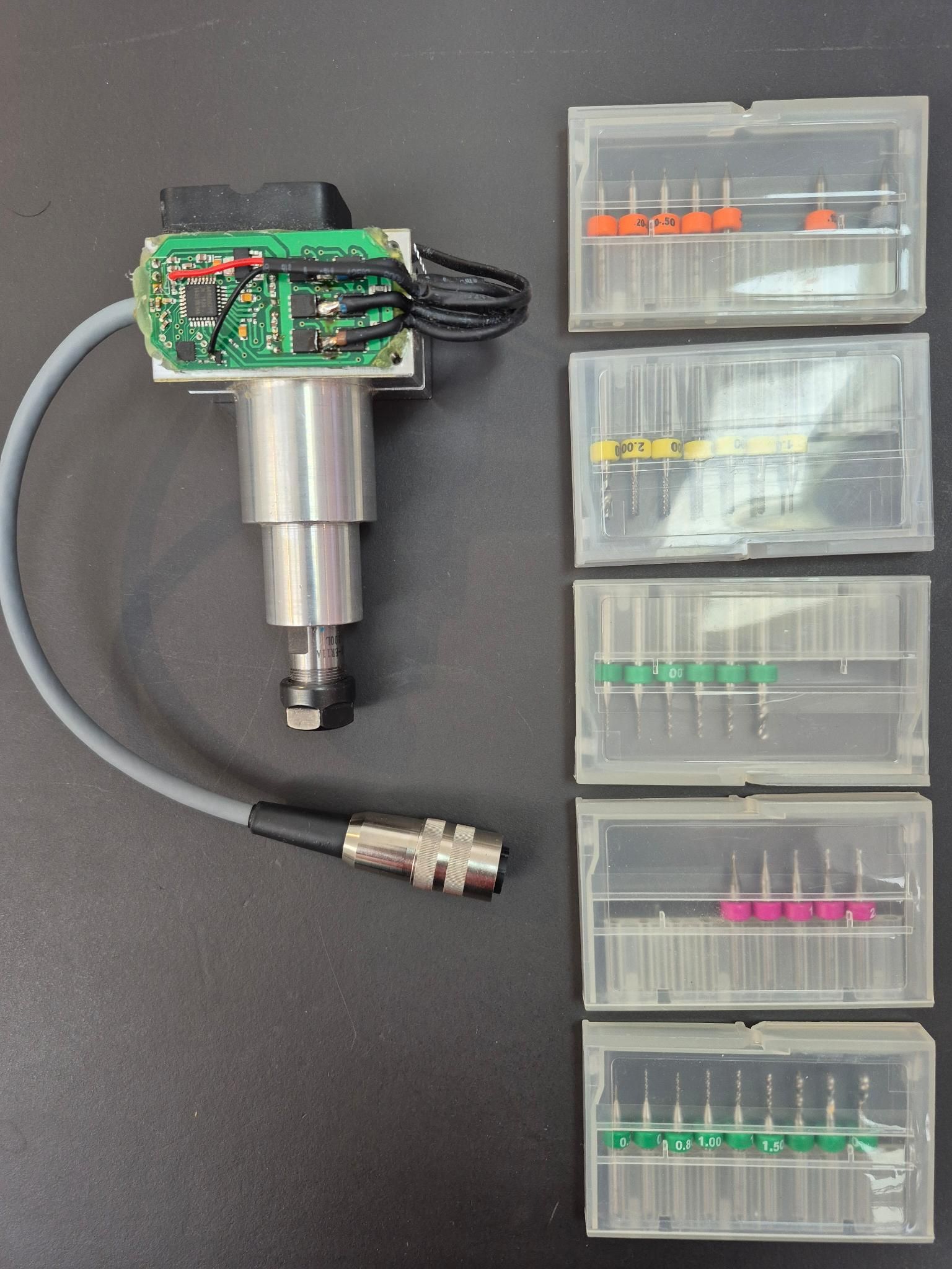
Solder paste head
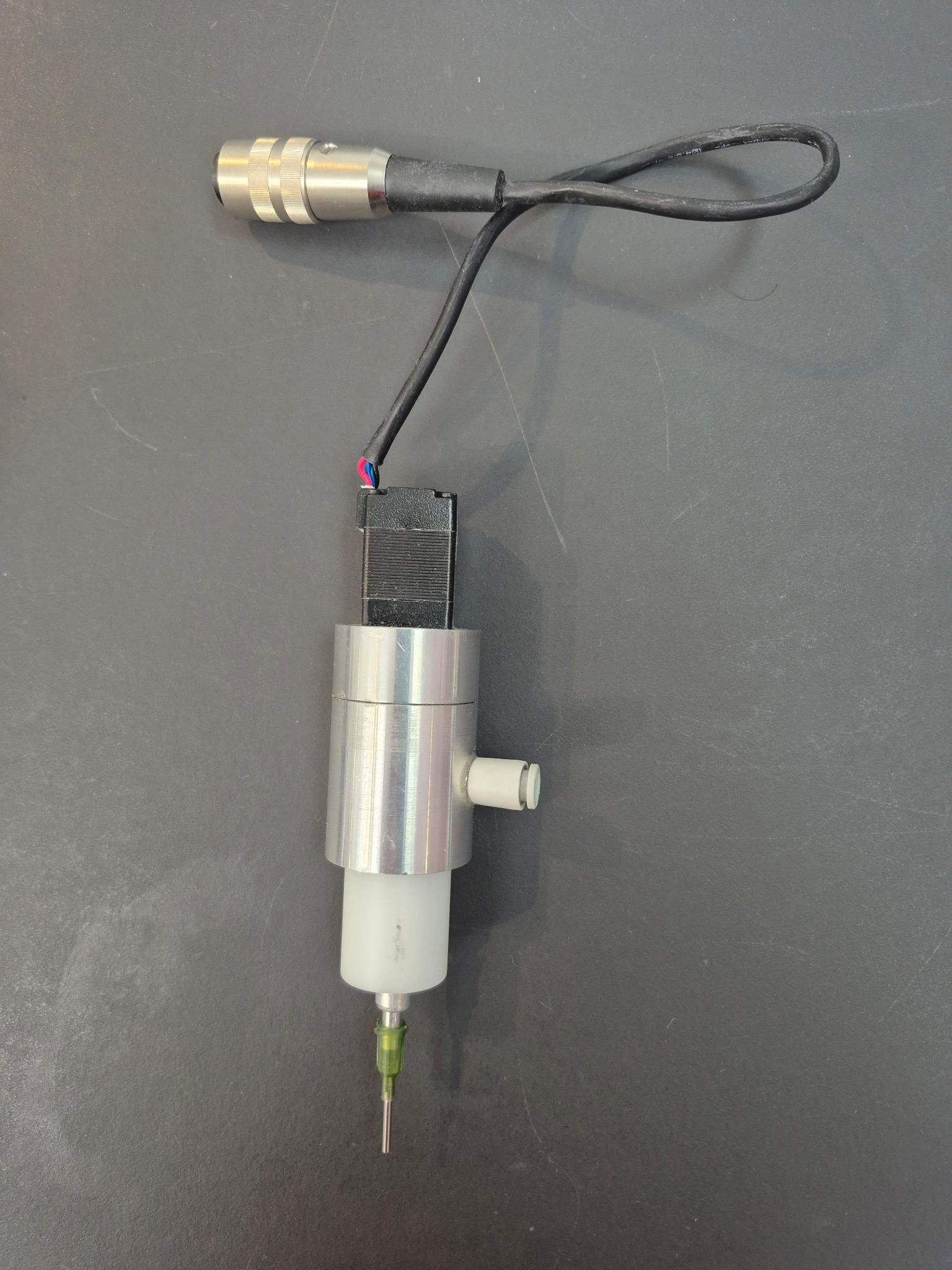
PnP head The 5the driver is for the motor for positioning
Mill and drill head
This was sold in 2016. It is really not badly designed. But I could not work with the software and never used this machine. Now have to mill small microstrip antennas. And that requires a lot of testing and milling. So this machine would speed up my development time for antennas a lot.
-
@Guus Interesting! As it has an STM32F407, you might be able to run RepRapFirmware on it via the STM port of the firmware: https://teamgloomy.github.io/.
@jay_s_uk might know if it would work, though it may take some effort to get it working, because you would have to define what the pins do. And the linear encoders would still not be supported in firmware.
And you have a Mini 5+ now, so probably not much point.
Ian
Bed-slinger - Mini5+ WiFi/1LC | RRP Fisher v1 - D2 WiFi | Polargraph - D2 WiFi | TronXY X5S - 6HC/Roto | CNC router - 6HC | Tractus3D T1250 - D2 Eth
-
@droftarts it won't run i'm afraid as it only has 512kb flash. not enough to fit RRF into (we're at about 730kb without the bootloader (another 32kb))
-
@droftarts said in Support for AS5311 High Resolution Linear Encoder:
@Guus The controller board is interesting. It looks like it has an ARM MCU, and the encoder plugs in directly to that. The stepper drivers are standard 'stepstick' plug-in modules, and are probably Allegro A4988 drivers. I'd guess the firmware reads the motor position from the encoder, and maybe adjusts the position, but this isn't quite closed loop, as it's not taking the motor commutation into account, which allows for accurate positioning. The drivers on the Mini 5+, even though in open loop mode, will be nicer!
Interesting that there are 5 drivers on the motor board. I guess it uses three for X, Y and Z. Does it use the driver with 8 output pins for Y? What does it use the other drivers for? I did see it comes with other tools, eg paste dispenser and pick-and-place toolhead, so I assume those.
Ian
There must have been many problems with this early design of the machine. The manufacturer panicked and stopped the production and closed down his company.
By installing a Duet 3 mini 5+ in this machine I have the latest and greatest controller and support!!!!! Thanks!!!!!
I won't be using the linear encoder for the time being. I will install 3 end stops on the machine. And I will install 4 Duet 3 Expansion 1HCL boards and 4 Duet 3 magnetic encoders. This way I will have a closed loop. The machine has robust spindles and I think the linear encoders are no longer necessary. So no new c code is needed.
If this setup is not accurate enough, I will try to figure out how to add the linear encoders to the machine.
Guus