Wiring BIQU microprobe to Duet RotoToolBoard
-
I don't need any heater nor fan on my tool this why I don't have such things.
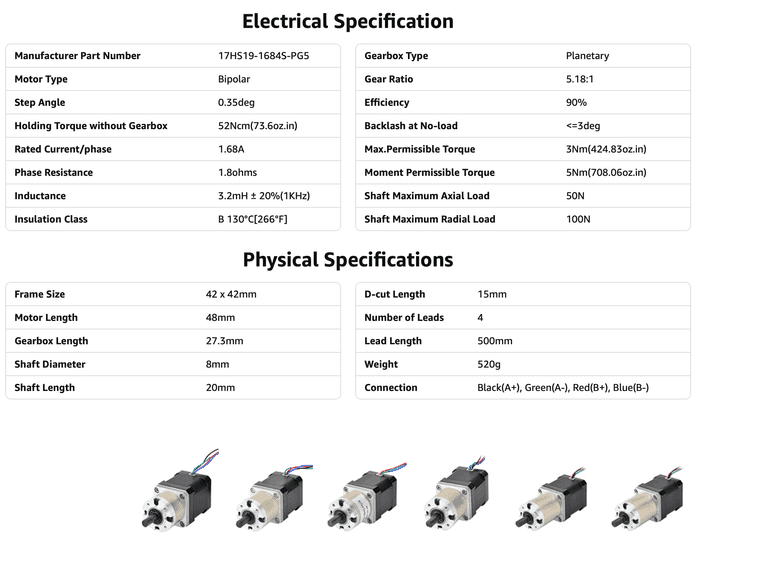
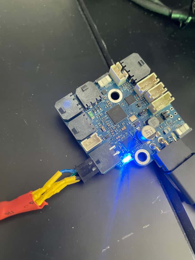
The cold extrusion command is part of my Gcode file though. However I'm testing the motor in DWC sending extrusion commands like G1 E10 F300. But this isn't working anymore...The motor is this one:
-
Hi,
The probe is not working at all except for the random deploy/retract - which is not a good thing.
Frederick
-
@fcwilt said in Wiring BIQU microprobe to Duet RotoToolBoard:
The probe is not working at all except for the random deploy/retract - which is not a good thing.
My guess is that either you have a bad connection in the control wire between the microprobe and the TOOL1RR, or the microprobe isn't compatible with the 3.3V signal level provided by the TOOL1RR. Have you a specification for the control signal required by the microprobe?
Duet WiFi hardware designer and firmware engineer
Please do not ask me for Duet support via PM or email, use the forum
http://www.escher3d.com, https://miscsolutions.wordpress.com -
@dc42 @Timothee-Leblond It does seem to need a 5V signal, see https://github.com/bigtreetech/MicroProbe/blob/master/MicroProbe V2 User Manual_20240330.pdf.
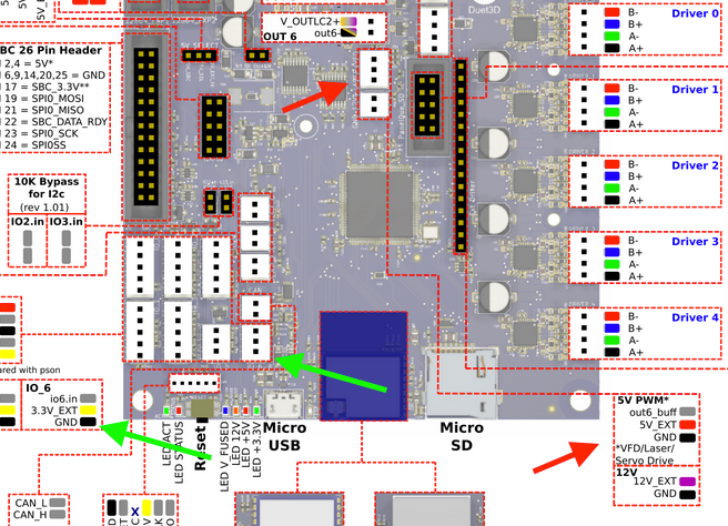
I would try connecting it to the Mini 5+ servo pin, and changing the probe setup. For wiring, see https://docs.duet3d.com/en/User_manual/Connecting_hardware/Z_probe_BLTouch#wiring but wire the servo control wire (and 5V and GND, if you want) to 5V_PWM header on the Mini 5+. Then change your config to:
; Probes
M950 P0 C"out6"                              ; Set servo output on Mini 5+
M558 P9 H6 F250:30 T8000 C"^!io6.in"            ; Set probe input to IO_6 on Mini 5+
G31 P500 X0 Y0 Z0                                  ; set Z probe trigger value, offset and trigger height
If possible, test your stepper motor on the Mini 5+ as well. If you can get that working, we can then look at why the Roto board isn't working.
Ian
Bed-slinger - Mini5+ WiFi/1LC | RRP Fisher v1 - D2 WiFi | Polargraph - D2 WiFi | TronXY X5S - 6HC/Roto | CNC router - 6HC | Tractus3D T1250 - D2 Eth
-
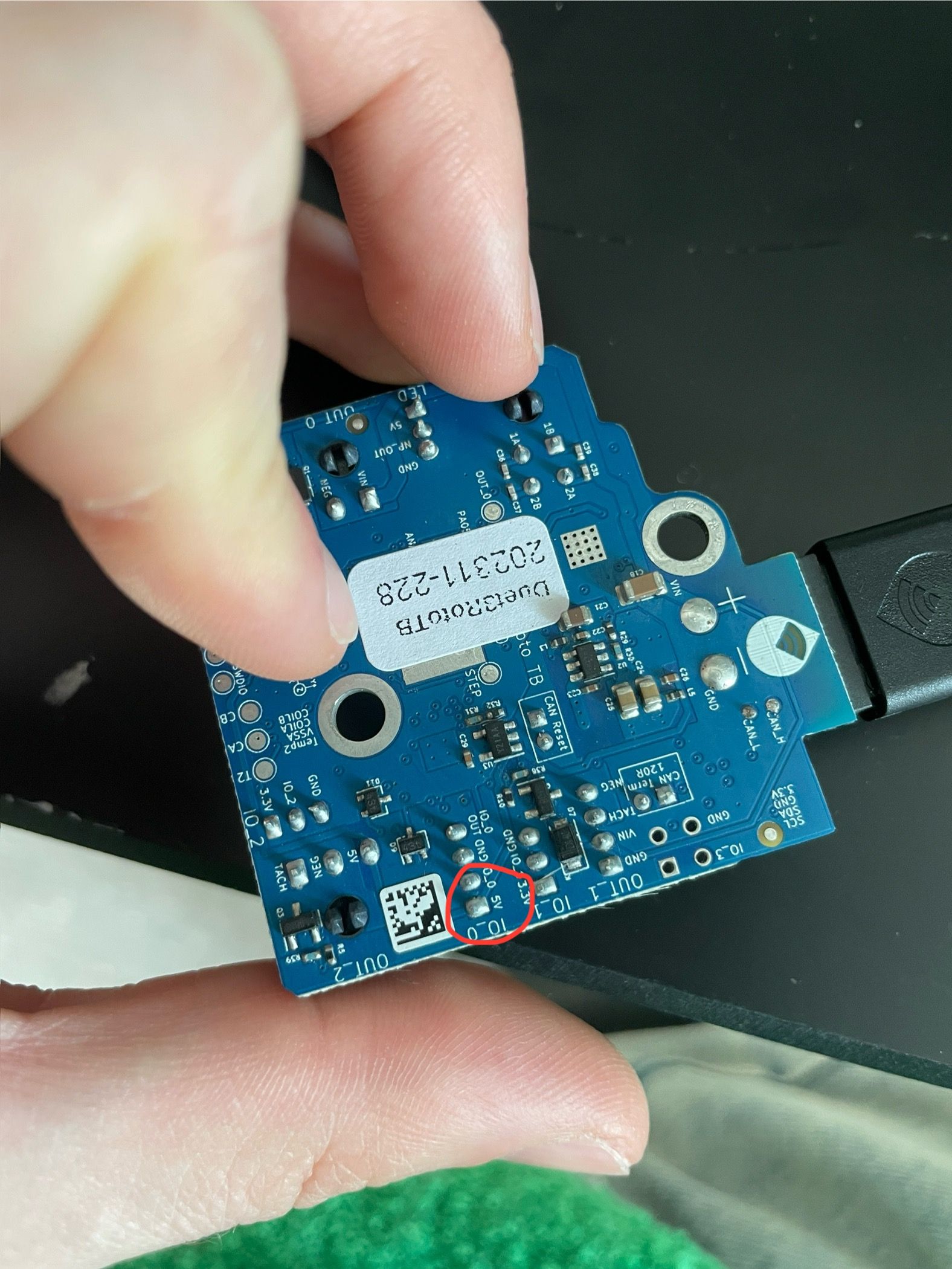
But what I can see, the pin on the Roto board is a 5V as well?
Sorry for my confusion but could you please point out the recommended pins on the wiring map?
As the wiring manual does indicate any duet board, I do not want to do any mistakes...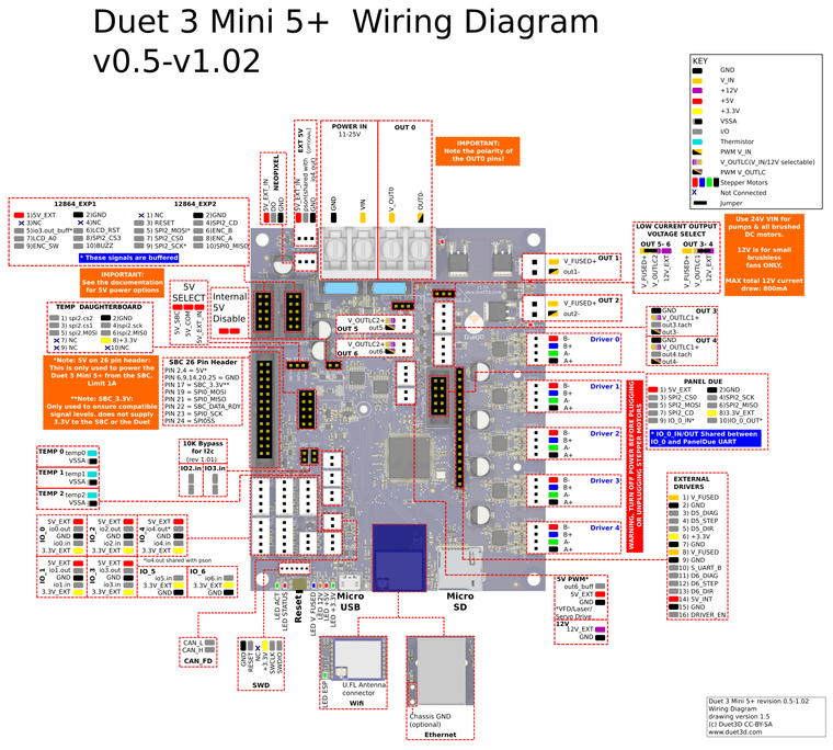
Thank you for your precious help!
-
-
@Timothee-Leblond said in Wiring BIQU microprobe to Duet RotoToolBoard:
But what I can see, the pin on the Roto board is a 5V as well?
The power provided on that pin is 5V but the signal level on the IO0_OUT pin is 3.3V. Most electronics devices these days (including BLTouch) are happy with 3.3V signal levels.
EDIT: according to https://biqu3d.com/blogs/news/biqu-microprobe-new-leveling-technology-that-defines-new-standards the microprobe is compatible with 3.3V control signals.
Duet WiFi hardware designer and firmware engineer
Please do not ask me for Duet support via PM or email, use the forum
http://www.escher3d.com, https://miscsolutions.wordpress.com -
Does this mean it is supposed to be working the way I initially wired it?
-
@Timothee-Leblond You need a 5V supply, and a separate 5V PWM signal to activate the probe. Currently you're using io0.out, which has a 3.3V signal level. Using the 5V PWM header (red arrows) for 5V, servo control (out6-buff) and GND, use IO6.in for the signal wire.
Ian
Bed-slinger - Mini5+ WiFi/1LC | RRP Fisher v1 - D2 WiFi | Polargraph - D2 WiFi | TronXY X5S - 6HC/Roto | CNC router - 6HC | Tractus3D T1250 - D2 Eth
-
Hallelujah! The probe is now working with this wiring! THank you!
About the stepper, any idea why it is not working? I know it has been working in the past wired this way to the Roto board.
-
@Timothee-Leblond said in Wiring BIQU microprobe to Duet RotoToolBoard:
About the stepper, any idea why it is not working? I know it has been working in the past wired this way to the Roto board.
Your config:
; Extruders
M584 E121.0 ; set extruder mapping
M350 E16 I1 ; configure microstepping with interpolation
M906 E1600 ; set extruder driver currents
M92 E28.09 ; configure steps per mm
M566 E120 ; set maximum instantaneous speed changes (mm/min)
M203 E3600 ; set maximum speeds (mm/min)
M201 E250 ; set accelerations (mm/s^2)
At 28 steps per mm, M92 looks wrong. If you extrude 1mm, the motor would barely move. As @Phaedrux said, the stepper driver is limited to 1A, so perhaps set M906 to E800. Does the motor get 'energised', ie can you turn it easily by hand after sending a command?
Ian
Bed-slinger - Mini5+ WiFi/1LC | RRP Fisher v1 - D2 WiFi | Polargraph - D2 WiFi | TronXY X5S - 6HC/Roto | CNC router - 6HC | Tractus3D T1250 - D2 Eth
-
Changing the E1600 to E800 and putting a higher value for M92 works.
Is there a way to set this up correctly? I mean finding the right value for the steps per mm?Thank you,
Tim
-
@Timothee-Leblond It depends on what extruder you are using. You said you don't have a heater, I think, so is it something custom? Ultimately you want it to pull in 1mm of filament when 1mm of extrusion is commanded. You can get a baseline figure by changing M92. For a guide, see https://docs.duet3d.com/en/How_to_guides/Calibration#h-3-calibrating-extruder-e-steps-per-mm
Ian
Bed-slinger - Mini5+ WiFi/1LC | RRP Fisher v1 - D2 WiFi | Polargraph - D2 WiFi | TronXY X5S - 6HC/Roto | CNC router - 6HC | Tractus3D T1250 - D2 Eth
-
@droftarts said in Wiring BIQU microprobe to Duet RotoToolBoard:
My tool is a bioprinter (cold extrusion) so I cannot really follow the guide infortunately. The system is as follows:
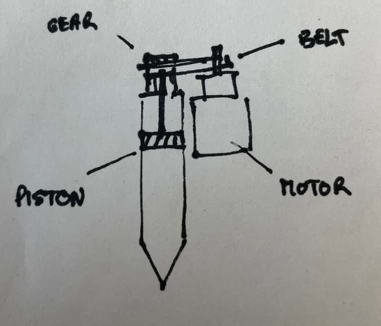
I actually don't know how am I suppose to configure the firmware for this.
Thank you,
Tim
-
@Timothee-Leblond You probably want to set it, at least to start with, as the number of steps for 1mm movement of the piston. It will be based on the size of the pulleys driving the belt (though if they are the same, can be ignored), and the thread pitch of the nut that drives the piston.
You can then work out the mm^3 you extrude for 1mm, by multiplying by the radius of the syringe (actually pi*r^2). You can specify extrusion in mm^3, see https://docs.duet3d.com/en/User_manual/Reference/Gcodes#m200-volumetric-extrusion.
Ian
Bed-slinger - Mini5+ WiFi/1LC | RRP Fisher v1 - D2 WiFi | Polargraph - D2 WiFi | TronXY X5S - 6HC/Roto | CNC router - 6HC | Tractus3D T1250 - D2 Eth
-
@droftarts said in Wiring BIQU microprobe to Duet RotoToolBoard:
the number of steps for 1mm movement of the piston.
The pulley driving the belt are of the same size.
So I have a T5 200mm (pitch of 5mm) belt. The pulley driving the piston has 20 teeth and diameter of 29.5mm. The pitch of the belt is 5mm which is the same as the pulley's pitch. The motor has a step angle of 0.35 with a gear box reduction of 5.18:1. So I end up with the following calculations:
Step per revs: 360/0.35 =1,028.571
Assuming 16x microstepping: 1,028.571*16=16,457.136 steps/rev
Applying gear box reduction: 16,457.136/5.18=3,177.0533
Pulley circumference: 20 (teeth)*5 (pitch)= 100mm
Steps per mm: 3,177.0533/100=31.771It is not much than the 24 mm I had before.. Am I omiting something in my calculations? Or maybe these are wrong?
-
@Timothee-Leblond I think your motor is this one: https://www.omc-stepperonline.com/nema-17-stepper-motor-bipolar-l-48mm-w-gear-ratio-5-1-planetary-gearbox-17hs19-1684s-pg5
That looks like a pretty standard NEMA 17 motor with a 5.18:1 gearbox on it. The step angle is 0.35 after the gearbox, because a normal NEMA 17 motor has a 1.8° step angle, so divided by 5.18 = ~0.35°.
1.8 step angle is 200 full steps per revolution. Multiply by the gear ratio of 5.18 = 1036 full steps per revolution after the gearbox. Multiplied by x16 microstepping is 16576 steps per revolution.
As I said, if your pulley are the same size, you can ignore them. One turn of the motor will be one turn of the piston screw. You need to measure how far the piston moves with one turn. Say it moves 5mm, then your steps per mm would be 16576 / 5 = 3315.2.
Ian
Bed-slinger - Mini5+ WiFi/1LC | RRP Fisher v1 - D2 WiFi | Polargraph - D2 WiFi | TronXY X5S - 6HC/Roto | CNC router - 6HC | Tractus3D T1250 - D2 Eth
-
@droftarts Got it. Thank you so so much for your precious help.
-
 undefined Timothee Leblond referenced this topic
-
undefined bass4aj referenced this topic