Duet 2 v1.02 not responding
-
@thomasvanderwal When the nozzle moves to different points on the bed during delta calibration, is it hitting the bed? Most likely it needs to lift higher between probe points. In your config.g, uncomment this line (remove ; from the beginning):
;M558 H30 ;*** Remove this line after delta calibration has been done and new delta parameters have been savedThe probe will lift higher between each probe point, so it won't hit the bed but will take a bit longer, but you should then get an initial calibration.
If that doesn't help, please post a video of what is happening.
Ian
Bed-slinger - Mini5+ WiFi/1LC | RRP Fisher v1 - D2 WiFi | Polargraph - D2 WiFi | TronXY X5S - 6HC/Roto | CNC router - 6HC | Tractus3D T1250 - D2 Eth
-
@droftarts Oke this seems to work.
But my print is still letting lose on the bed. What can I do about that.
Temp bed is 60deg. Or is PLA not good anymore -
@droftarts what about M557?
For a round printbed diameter 20cm?
M557 R95 S30
is this a good approach (chatgpt)?
-
@thomasvanderwal said in Duet 2 v1.02 not responding:
But my print is still letting lose on the bed. What can I do about that.
Temp bed is 60deg. Or is PLA not good anymore60C should be fine for PLA. Make sure the bed is clean, use Isopropyl alcohol to clean it. What is the bed surface? It seems to be textured?
what about M557? For a round printbed diameter 20cm?
M557 R95 S30That will give a reasonable grid for bed mesh, with 7 points across the bed. You could reduce the spacing to S20. I prefer to use the P parameter to specify the number of points, eg
M557 R95 P7, as it will space out the points up to the limit. See https://docs.duet3d.com/en/User_manual/Reference/Gcodes#m557-set-z-probe-point-or-define-probing-gridis this a good approach (chatgpt)?
I generally wouldn't use 'AI' for RRF config and code. It rarely gets it 100% correct.
Ian
-
@thomasvanderwal said in Duet 2 v1.02 not responding:
But my print is still letting lose on the bed. What can I do about that.
After running delta calibration, manually jog the nozzle down until it just touches the bed, then look at the coordinates to see how close to Z = 0 it is. Even better, jog the nozzle until it just traps a thin feeler gauge between the nozzle and the bed, and then see how the displayed Z height compares with the thickness of the feeler gauge. Do this both at the centre of the bed and at several places around the bed (ideally at each point at which you probe the bed during delta calibration).
If the indicated height is consistently too large or too small then adjust the G31 H parameter to correct it.
If the difference between expected and indicated height varies greatly between different probe points, then you most likely have a probe system that does not have a consistent trigger height, and you should try to fix that.
Can you explain what the issue is with the bed clips? I presume they are supposed to hold the bed securely on the support below; in which case I don't see anything wrong with the one on the right in your photo. The bends in it look deliberate to me.
Perhaps it's better to continue this in a new thread, because the issue being discussed has moved a long way from the thread title.
Duet WiFi hardware designer and firmware engineer
Please do not ask me for Duet support via PM or email, use the forum
http://www.escher3d.com, https://miscsolutions.wordpress.com -
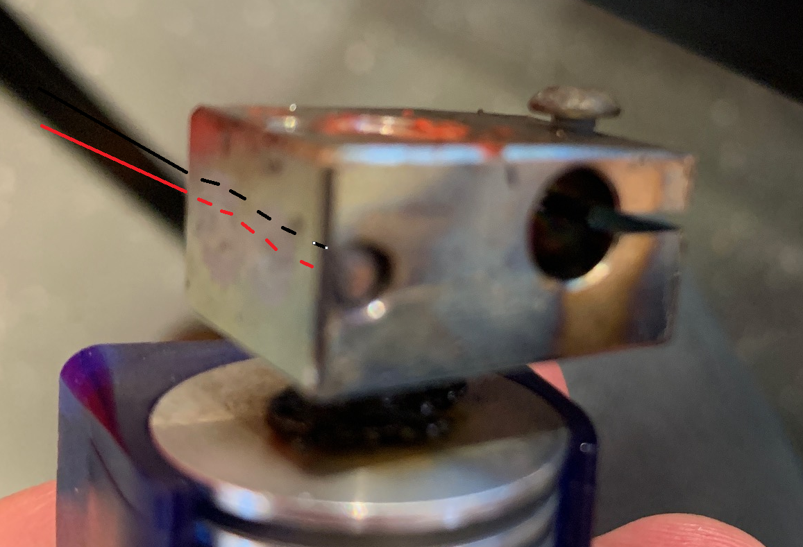
@dc42 Another problem. I had to change the cilinder and the heat block. Now it gives : Heater 1 fault: failed to read sensor: hardwareError
The heater gives 2000deg C. The 2 wires of the thermistor where lose in the heat block.
I connected the wires like this. So it doesn't toch the heat block.
-
@thomasvanderwal a reading of 2000C usually means that the wires are either shorted together or one of them is shorted to the heater block. What are those blue sleeves made of - can they take the heat?
Perhaps it's time to get a new thermistor. Is it definitely a thermistor? The M308 command for that sensor in config.g will specify the type of sensor.
Duet WiFi hardware designer and firmware engineer
Please do not ask me for Duet support via PM or email, use the forum
http://www.escher3d.com, https://miscsolutions.wordpress.com -
@dc42 Sensor 1 type PT100 (MAX31865) using pin spi.cs1, last error hardwareError, reading 2000.0, 2/4 wires, reject 50Hz, reference resistor 400.00 ohms
-
@thomasvanderwal so it's a PT100 sensor connected to a daughter board on the Duet. The 2000 reading is because it's reporting "hardware error". I suggest you try the following:
- Check that the daughter board is properly seated on the Duet and the nylon support peg is in place.
- Disconnect the PT100 sensor from the daughter board (make a note of which wires go to which terminals first). Then power up the Duet. If it still reports "hardware error" then the daughter board is faulty. in which case, you could try the other daughter board channel if it is free. That one uses pin spi.cs2 instead of spi.cs1.
Duet WiFi hardware designer and firmware engineer
Please do not ask me for Duet support via PM or email, use the forum
http://www.escher3d.com, https://miscsolutions.wordpress.com -
@dc42 still this even I plugged it to spi.cs2 and changed the code M308 S1 P"spi.cs2" Y"rtd-max31865"
Heater 1 fault: failed to read sensor: hardwareError
-
-
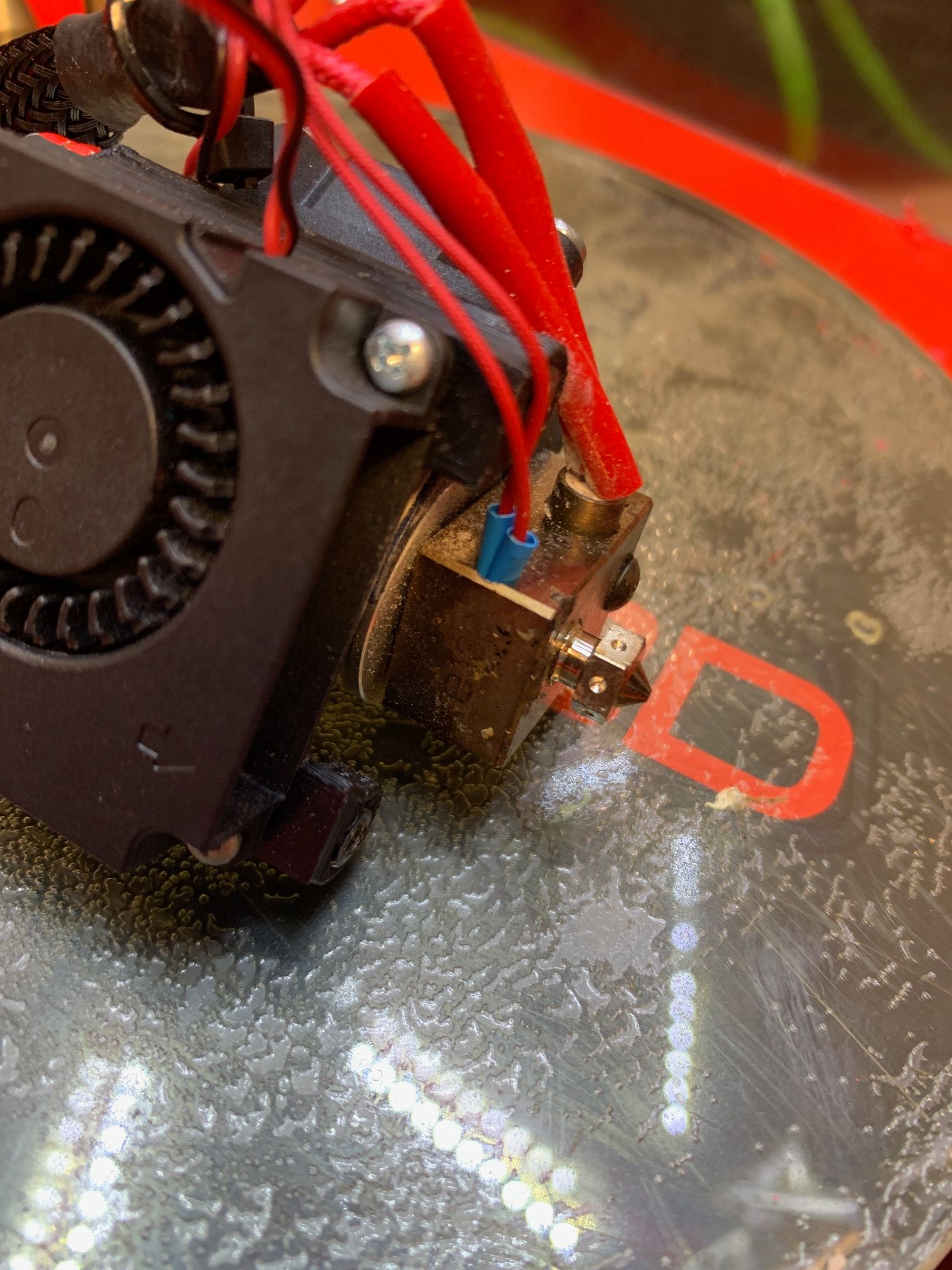
@thomasvanderwal You have assembled the hot end incorrectly. The nozzle shouldn't be sticking out this far, and the heater block should not be touching the heatsink:
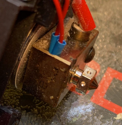
This looks like an E3D V6 hot end. See https://e3d-online.zendesk.com/hc/en-us/articles/360017013257-V6-Assembly-Guide-Edition-2
When you replaced the hot end, did you replace the temperature sensor as well? Remove it from the heater block to be sure it's not shorting there (there's a grub screw holding it in, see the instructions above), disconnect it from the Duet, then measure the resistance of the temperature sensor with a multimeter. The reading at room temperature should indicate what kind of temperature sensor it is.
Ian
Bed-slinger - Mini5+ WiFi/1LC | RRP Fisher v1 - D2 WiFi | Polargraph - D2 WiFi | TronXY X5S - 6HC/Roto | CNC router - 6HC | Tractus3D T1250 - D2 Eth
-
@droftarts aha oke the wires are lose from the temperature sensor. Is this fixable?
-
@thomasvanderwal Is this the original temperature sensor? Either crimping or soldering may repair it.
Ian
Bed-slinger - Mini5+ WiFi/1LC | RRP Fisher v1 - D2 WiFi | Polargraph - D2 WiFi | TronXY X5S - 6HC/Roto | CNC router - 6HC | Tractus3D T1250 - D2 Eth
-
@droftarts do you know how? When the two wires Connect I get as circuit error.
The sensor itself is a resistor? So soldering without touching eachother? -
@thomasvanderwal I'll ask a third time; is this the original temperature sensor, or a different one? Maybe post a picture of the temperature sensor, removed from the heater block. Yes, the wires should be soldered without touching each other, and be insulated from the heater block. Replacement PT100 temperature sensors (as well as PT1000 and thermistors) are available from E3D: https://e3d-online.com/products/pt100-temperature-sensor
The temperature sensor is a type of resistor, but the resistance changes with temperature. PT100, PT1000 and thermistors are different, and need to be setup differently in config.g.
A PT100 has a resistance of 100 ohms at 0C, see the resistance table here https://www.sterlingsensors.co.uk/pt100-resistance-table
A PT1000 has a resistance of 1000 ohms at 0C, see the resistance table here https://www.sterlingsensors.co.uk/pt1000-resistance-table
A 100k thermistor has a resistance of 100000 Ohms at 25C, for example see the resistance table here https://www.bapihvac.com/wp-content/uploads/2010/11/Thermistor_100K.pdfNote how the PT100 and PT1000 resistance increases with increasing temperature, while the thermistor resistance decreases with increasing temperature. This is why it's important to correctly identify what temperature sensor you are using. Please measure the resistance of the temperature sensor with a multimeter at room temperature.
Ian
Bed-slinger - Mini5+ WiFi/1LC | RRP Fisher v1 - D2 WiFi | Polargraph - D2 WiFi | TronXY X5S - 6HC/Roto | CNC router - 6HC | Tractus3D T1250 - D2 Eth
-
The sensor itself is a resistor? So soldering without touching each other?
Solder joints iin the immediate vicinity of a hotend which can easily reach the temperature of a soldering iron? Perhaps not the best idea. Better replace the temp sensor with a new one. There’s a reason why these come with heat resistant connection cables.
-
@droftarts oh sorry, it is a spare. So I think it is a original. An thank you for your patience. Due to lack of time I'm on and off with this printer conquest.
-
@thomasvanderwal So it may not be a PT100. PT1000 and thermistors connect directly to the Duet, not through the temperature daughterboard. The only way to know is to measure the resistance.
If you can refit the original temperature sensor, that's probably the easiest thing to do. If you look at the hot end assembly guide I posted earlier, you'll see how the temperature sensor is secured in the heater block by a grub screw. Loosen that, replace the temperature sensor with the original one.
Ian
Bed-slinger - Mini5+ WiFi/1LC | RRP Fisher v1 - D2 WiFi | Polargraph - D2 WiFi | TronXY X5S - 6HC/Roto | CNC router - 6HC | Tractus3D T1250 - D2 Eth
-
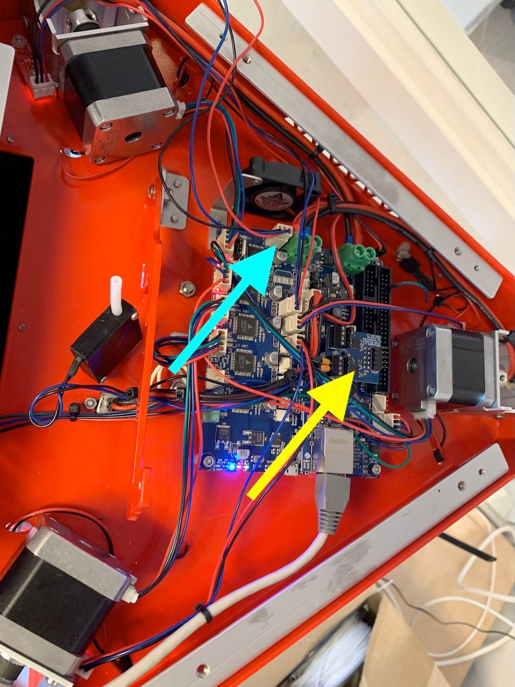
You can see my daughterboard (yellow arrow). I ordered a PT100 for a e3D.
-
 undefined droftarts referenced this topic