[feature] Adaptive / Feedforward Temperature setpoint
-
@Adrian52 I found that the active (=target) temperature is not updated, either in DWC or in the Paneldue. It is impossible to know how far the current temperature deviation is.
Besides, I had to increase the S Parameter to about 0.3 to get a quicker change of temperature. Nontheless, I get heater faults from time to time, although I have loosened the check using the command M570 H1 P100 T45, which is incredibly forgiving, as it allows a deviation of 45 C deg to persist for up to 100 sec...
-
@Triet I guess if one is using the feedforward in the way intended, the temperature shown is the target temperature. I have been playing with the parameters, trying to understand how they work. I am trying out a 0.25mm nozzle, which has an extrusion rate of about 8.8cumm/sec with 0.125mm layers at 140mm/sec, which is think corresponds to about 3.6mm/sec for 1.75 filament. A T parameter of 12 seems to give the expected increase of just greater than 40deg over the base temperature. I think there is a bit of under extrusion at this speed with the 0.25 nozzle, but checking that out. For my standard 0.4 cht nozzle, 0.2 layers give about 22cumm/sec at 140 mm/sec, that is about 9mm/sec filament. Using T5, this gives the expected increase of about 45deg above base temperature. I dont think the cht nozzle is underextruding under these conditions. I have just started using an S parameter of 1.0, and this seems to work fine with the 0.25 nozzle - not tried with the 0.4 nozzle yet. Tried increasing the A parameter to 50, and the feed forward stops working.
I have been using M570 H1 P15 T45, and not been getting heater faults. The revo nozzle setup I am using has a low thermal mass, and seems to be controlled very well by the duet. -
@timschneider said in [feature] Adaptive / Feedforward Temperature setpoint:
ok, A40 is working - but shouldn't A100 act like A0 if A100 can not be maintained? Instead it was acting like T0.
I've reduced the maximum allowed from A100 to A50 in rc2, which I think should work.
[EDIT: Adrian's post above suggests that it doesn't.]
Duet WiFi hardware designer and firmware engineer
Please do not ask me for Duet support via PM or email, use the forum
http://www.escher3d.com, https://miscsolutions.wordpress.com -
@Adrian52 said in [feature] Adaptive / Feedforward Temperature setpoint:
I guess if one is using the feedforward in the way intended, the temperature shown is the target temperature
That's correct, the target (as displayed by DWC and PanelDue) remains the same but the feedforward correction is added to it internally.
@Triet said in [feature] Adaptive / Feedforward Temperature setpoint:
It is impossible to know how far the current temperature deviation is.
I'll look at adding the current feedforward boost to the object model.
EDIT: I've added the boost parameters to the OM.
-
@dc42 On my system, the highest A value that works is 48
-
To see if I could get the hotend to follow the forward temperature more closely, I tried removing the silicone sock from the revo heater, to see if I could get faster cooling. I redid the pid tune without the sock, and this is the plot printing a 100mmx20mm cube that has three small cylinders attached to one end. The cube walls print at 140mm/sec, and the cylinders around 20mm/sec. The cube has no fill or top, but the initial part shows printing the bottom infill
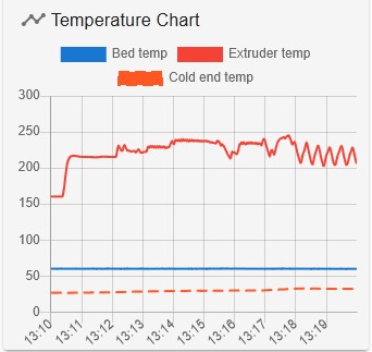
It then cycles between the fast cube walls and the slow cylinder walls. I was suprised how well controlled the temperature is under these conditions. The print weighed exactly the amount predicted by the slicer, so no underextrusion. The cube walls were printing at 22cumm/sec (o.4 nozzle, 0.2layers). The S parameter was set to 1
Would be interesting to plot the feed forward boosted temperature on the temperature chart - is this possible?
-
@Adrian52 you could plot it with BtnCmd if its in the object model
-
@Adrian52 Wouln't you need to repeat the same print (with/without silicon sock) to properly quantify the effect? What are you comparing to?
-
@Triet Indeed - I was just looking at the feasibility of leaving off the sock. I was concerned that it would make temperature control unstable, but this doesn't seem to be the case. I thought a next step would be to plot the boosted temperature against the actual temperature, but waiting for an update that has the boosted temperature in the OM. On a learning curve with btncmd too - not used it before. Will aim to do a more formal comparison, including maximum speed and print quality.
-
@Adrian52 I share the same interest. If I get somewhere customizing DWC to show the temperature deviation I will post my findings.
By the way, removing the silicon sock to facilitate better temperature control is a brilliant idea.
-
@Triet said in [feature] Adaptive / Feedforward Temperature setpoint:
By the way, removing the silicon sock to facilitate better temperature control is a brilliant idea.
Even better would be to replace the hot end by one with much lower thermal mass and heating/cooling times, such as the E3D Revo.
Duet WiFi hardware designer and firmware engineer
Please do not ask me for Duet support via PM or email, use the forum
http://www.escher3d.com, https://miscsolutions.wordpress.com -
@dc42 I am in fact using a revo micro on my delta, and just ordered a 60w heater, to see if it shortens the heating time. Hope it doesn't melt my part cooling duct!
-
@dc42 The thoroughgoing extrapolation of this idea would be an
INo Trident -
Another experiment, with a 60W e3d revo heater, and no socks. The print is a 20x100mm cube, and a set of 6 8mm diameter cylinders. The cylinders print quite slowly and the cube at 140mm/sec.
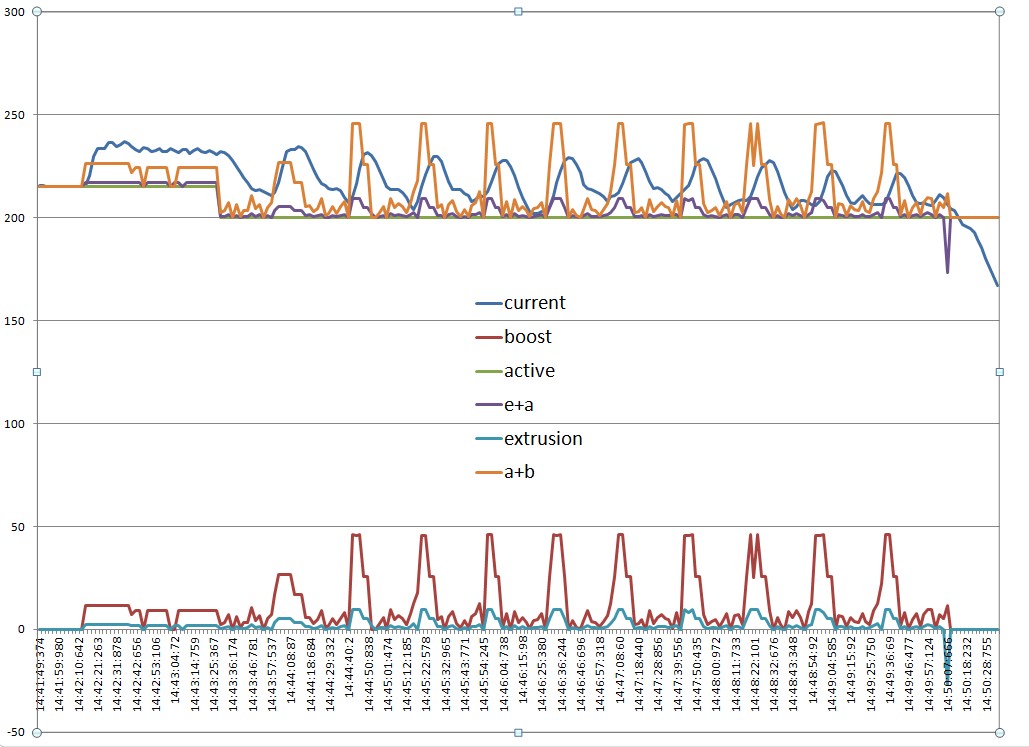
This is an excel graph of csv data captured by btncmd (not worked out how to plot calculated values in btncmd).
I added the active temp to the boost (a+b) to compare to the actual temp(current). You can see there is a bit of a lag on both the heating and cooling phases.
I also plot the extrusion volume, and you can see that the boost anticipates the increase in extrusion, although not by enough to align with the current temperature. I plotted extrusion+active temp(e+a) to move the extrusion line up to the area of the current temp line.
Not quite sure why the active +boost is below the current temperature in the initial phase - this is the relatively slow printing of the first layer. -
@Adrian52 If the command would allow an option to limit the extrusion (=speed) to match the actual temperature, it would be much better, as layer adhesion would be optimal. Delamination and sudden breaks under mechanical load would be a thing of the past.
-
@dc42 the 60w heater on the revo seems to work fine, albeit with a tendency to overshoot a bit. The heat /cool curve (current) is not too bad, but lags the extrusion /boost curves by about 6 seconds. I tried increasing the queue size to 120, which is probably near the limit for my old duet2wifi. The A parameter at 50 works then. Is there any way to adjust for the lag?
-
@Adrian52 you should be able to reduce the overshoot by increasing the M307 R parameter a little.
RRF only knows exactly how a move will be performed about 50ms before it is executed, so unfortunately values of advance higher than 50ms are not possible.
Duet WiFi hardware designer and firmware engineer
Please do not ask me for Duet support via PM or email, use the forum
http://www.escher3d.com, https://miscsolutions.wordpress.com -
@dc42 Have been wondering if a post process would be possible, and came across this article
https://www.nature.com/articles/s41467-025-56140-1#MOESM1
A rather impeccable source - maybe this is the way things might develop. -
@Adrian52 I actually went through that article. I understood the basic postulates, and I even believe in the results, but why didn't the authors use regular filament material? I doubt the relevance for regular 3D printing. And you would need a T-Code slicer on the long run to avoid resync operations.
-
@dc42 I am astonished that a firmware with such a blatant limitation works so well nontheless. In my naivity, I always assumed a way farther advance scope. Processing the whole loop or all contiguous segments (not necessarily the whole layer) would be optimal, as all movements belonging together could be handled more consistently. Is RAM nowadays such a scarce asset?