Duet3D Logo Duet3D
    • Tags
    • Documentation
    • Order
    • Register
    • Login
    1. Home
    2. Triet
    • Profile
    • Following 0
    • Followers 0
    • Topics 23
    • Posts 139
    • Best 9
    • Controversial 1
    • Groups 0

    Triet

    @Triet

    12
    Reputation
    8
    Profile views
    139
    Posts
    0
    Followers
    0
    Following
    Joined Last Online

    Triet Unfollow Follow

    Best posts made by Triet

    • RE: [feature] Adaptive / Feedforward Temperature setpoint

      @dc42
      I dared to try 😊

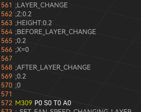
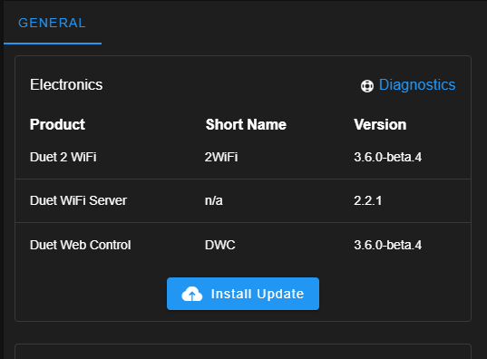
      Using firmware version 3.6.0-beta.4 and with following command in my config.g:
      M309 P0 S0.06 T10 A40
      I can confirm that temperature modulation based on flow rate works.

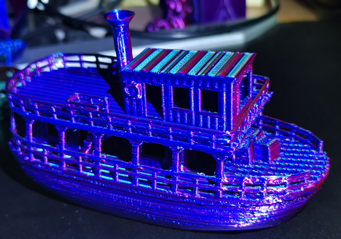
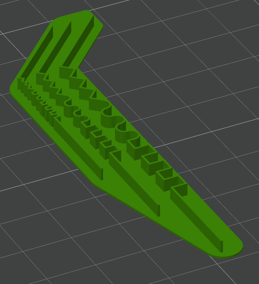
      I used the small model below as a preliminary experiment, printed at a nominal temperature of 190 deg C. (usually I print this material at 212 deg C).

      Remarks:
      During the first layer the temperature jumped to over 220 deg C but with the bed at 45 deg C this was unnecessarily high to achieve bed adhesion. To avoid such surprises I managed to disable this feature for the first layer alone using
      the macro command
      M309 P0 S{(layer_num == 0 ? 0 : 0.06)} T{(layer_num == 0 ? 0 : 10)} A{(layer_num == 0 ? 0 : 40)}
      which yields M309 P0 S0 T0 A0 for ths 1st layer only; then the temperature set for the 1st layer in the slicer is used unchanged.

      I needed several retries because I was getting a heater fault error right at the 1st layer. The increase was too sudden I guess. Only after I reconfigured the heater fault detection I could continue the print:
      M570 H1 P15 T20 ; wait 15 sec, allow 20C deviation

      The maximum temperature increase happened at the widest height of the model and was about 5 degrees, but only a short time.
      Most of the time the print temperature stayed around 192C, that is, only 2 degrees higher than set. Although the speeds were set up to 300 mm/sec, due to a layer time limitation and weak cooling fan, the print went quite slow with 20-35 mm/sec.

      The deviation between target and actual temperatures can't be assessed during the print, because the increase introduced by this feature is done in the firmware - this is as expected, but raises the need of a plug-in in DWC to preview the effect.

      Manually overriding the extrusion speed live during the print (or perhaps using M220) did cause a corresponding increase in temperature, as it should be.

      It is unclear to me whether extrusion rate increases caused by non-linear extrusion configuration (M592) also cause temperature increases. In theory, his could lead to a vicious circle, because a temperature increase by itself also promotes a higher extrusion.

      I learned that this feature works only increasing the temperature, never decreasing it. That means that one is compelled to choose a nominal printing temperature (the one set in the slicer) that should be low enough that no decrease is necessary due to a smallish flow. This could happen to be inconvenient, depending on the average flow and temperature range needed. This method is suitable to adapt temperature in regions with higher flows, overcoming potential bottlenecks.

      A better approach would have been (in my opinion) to consider the nominal temperature to correspond to the average flow rate, allowing both increases and decreases. In most cases no special tests or calibrations would be needed with this method; for example, setting 205C for PLA, thus allowing a range of +/- 15C=30C. Flow rate "spikes" would be still accounted for. This way, small details and overhangs would benefit too (a more common concern than printing at very high speeds, if quality is important).

      In other words, as it is implemented, you would set for a benchy a nominal temperature corresponding to the chimney top - suboptimal I think.

      Print details:
      Duet 2 WiFi + 0.4 nozzle, PLA, 0.12 mm layer height, 0.3 mm layer width, one wall only (to challenge the operation!)

      e0a8ceed-9e67-409b-a9c0-4b6371f6e37d-image.png

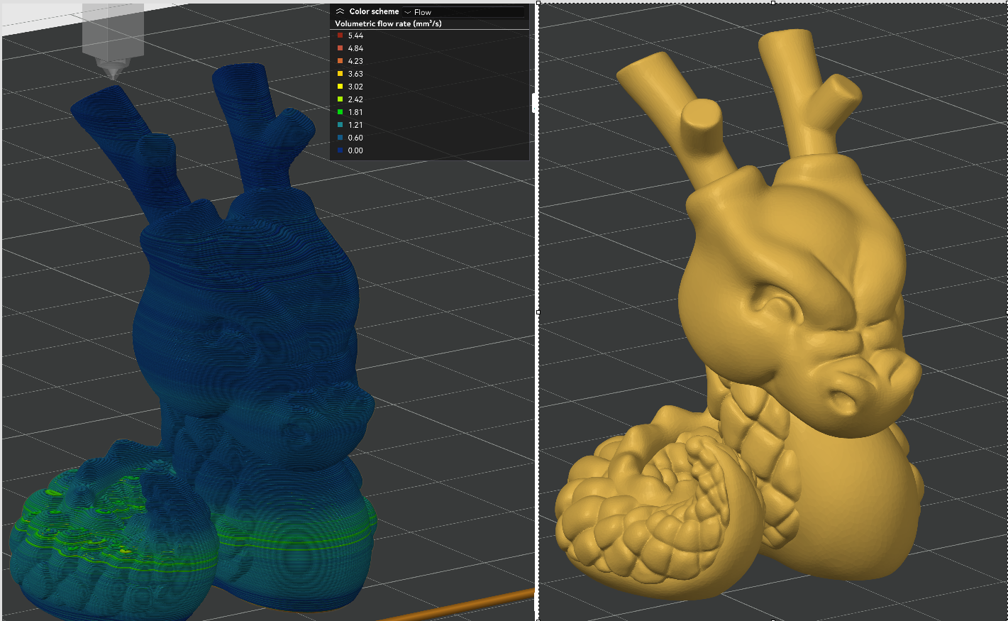
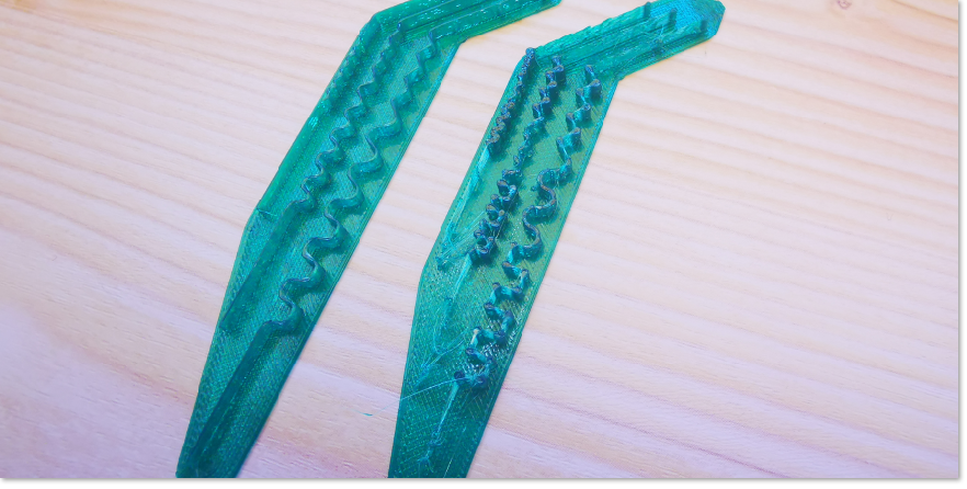
      And I got this result:
      dce88bc0-2579-4ec9-8327-d77db4974289-image.png
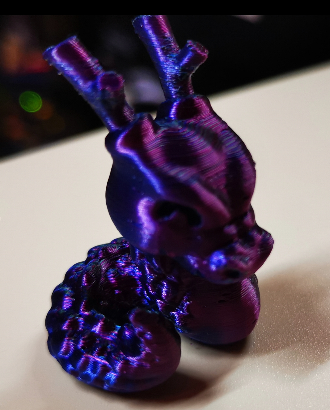
      The print was quite good in my opition, and was not worst than a good one done without the feature under same conditions. Still learning.

      I have gathered some experience using the post-processing script mentioned above. It is difficult to believe how felicitous that script manages the temperature/flow relationship. That solution works differently though: It controls speeds in such a way that the flow matches the temperature when the temperature can't be changed fast enough; it also smoothes the flow rate - sounds dangerous, but works surprisingly well. Unfortunately, it is only a post-processing script with the respective disadvantages. The author was told that such feature belongs to the firmware realm - here we have it.

      I think this feature of the version 3.6.0 will be vastly underestimated. I consider it a big jump, really.

      By the way, the description in the documentation of M309 should be corrected. It states:
      "This feature is intended for high flow hot ends or pellet extruders. It's not normally needed on regular hot ends with a 0.4mm or similar size nozzle where the temperature drop caused by extrusion is less than 1C."
      The feature may be inteded as described, but it is not limited to mere anticipation of temperature fluctuation of the nozzle due to changing flow. In fact, it contributes to a much better control of a key parameter, namely temperature. I myself will be using it quite often, I think.

      Hope I helped a bit.

      posted in Firmware developers
      Trietundefined
      Triet
    • RE: Need a 0.5 sec UPS (prolonging agony for resurrection)

      @dc42 I wanted to wrap up some informations about this topic but found that I am not allowed to post links - I need two "reputations".

      That's a pity. Would anyone be so kind to enable posting links for me? At least for this time. (Assuming that my findings are of general interest for the furure).

      posted in Duet Hardware and wiring
      Trietundefined
      Triet
    • RE: [feature] Adaptive / Feedforward Temperature setpoint

      @timschneider That model (I would call it "the "mother of hinges"), went well - all hinges were moving free without play (after forcingly "unfreezing" them the first time). I can infer then than the temperature variation does not pose a danger in maintaining correct dimensions, in this case at least.

      Now I am choosing a more representative test model with an ample variation of flow rate, which at the same time allows us to assess artifacts, without being excessive large or long to print.

      This JUN - the Jungle Queen (visual benchy) has a plethora of details and is not too small.
      9795afc6-ec9a-465f-b405-7b964b4f8f57-image.png

      Results:
      Printing with at 195 C, 0.2 mm layerheight, (0.4 mm nozzle), solid infill with 0.6 mm layer width, and sparse infill speed set at 300 mm/sec (but not reached) and still using M309 P0 S0.06 T10 A40, Orca Slicer was showing a flow rate up to 29 mm3/s, but that is not true. The real maximum is about 20 mm3/s, enough of a range. Extrusion rate smoothing was set to 90 mm3/s to avoid abrupt transitions.

      f6e2f2fc-d707-4a10-a131-f25293c494dc-image.png

      The temperature occassionally reached >240 C in the high flow areas. In very slow areas, it was decreased (!) down to 190 C. Most of the time, is was about 200C.

      The print shows very crisp details, reminding me of previous cases using the postprocessing script. This is obviously the result of printing the small details with a suiting lower temperature.

      85ebf392-91fc-456c-8d64-9940147d440b-image.png

      Despite some suboptimal slicer settings (happens when printing in a hurry), the print went well and it looks better than in the picture.

      Remarks:
      I noticed that right at the begin of the print the temperature is higher than it should be (although I disabled this temperature modulation feature for the first layer), but immediately begins to fall as the print of the 1st layer progresses. My suspicion is that the firmware looks at the flow of the movements in the print queue in advance, but ignoring the command disabling the feature. But the command it is there:
      e3135aaf-ad8f-414a-846a-67156613d44c-image.png
      and when it is processed, the temperature fails again to the nominal 195C. It looks like a slip to me.

      Furthermore, I still got heater faults (even after releasing the check conditions), but strangely, this happened at a moment where the temperature was quite stable after having significantly changed before. So it looks to me like the firmware notes a temperature deviation, but does not update that deviation timely as the temperature has changed and stabilized. Perhaps that part of the firmware should be revised.

      This time, a decrease in temperature compared to the nominally set print temperature (195 C in this case) took place at some point. So I withdraw the objection I made before, although I don't quite understand how this is controlled in detail. I assume that the T parameter defines a slope determined by changes of temperature in relation to changes in flow, but where we are in that characteristic curve, I don't know.

      Summarizing, I am very pleased with this enhancement. I still stand on my prediction that this feature will stay extremely underrated. I recommend to try it out.

      posted in Firmware developers
      Trietundefined
      Triet
    • RE: [FW 3.5.2] High jerk good for circular path not for corners

      @leone Let me add the following:
      below you will see a test model consisting of two connected half-circles, where the outer one is part of the original model, and the inner one was added by me as a part of a cylinder in order to compare.

      Using firmware 3.5.4, the outer curve was printed with jerky movements, and the print was showing vertical ripples. In this case though the ripples were caused by the model itself, as it is coarsely facetted - you can even recognize the straight lines building the outer curve. I just disliked that the printhead was stuttering. On the other hand, the inner half-circle was printed smoothly, no matter which jerk values I used; its resolution was way higher. All in all, everything was printed as it should, with the exception of the apparent small stops at the junctions of the outer circle, which was causing jerky movements, but the half-circles were printed both OK.
      6a58f017-4abb-4792-bb76-3fdd519b79c9-image.png
      Now using 3.6.0-beta.4 firmware version, even the outer half-circle is printed smoothly! I mean, there are no jerky movements anymore, but what is more astonishing: the print itself shows no vertical ripples anymore!! (But it should, actually). It is printed as a perfect curve, although it is not! No facettes are recognizable at all. In other words, some kind of smoothing of the surface took place (but looking at the gcode, no arc fitting was applied). I would say, this firmware is "cheating", but in a positive way. The print was improved beyond any expectation.

      Shouldn't that raise even some fidelity concern, I am asking myself now 😊

      Let me express the kudos that @dc42 and developers deserve. Version 3.6 is going to be a big throw indeed. I am perplexed.

      posted in Tuning and tweaking
      Trietundefined
      Triet
    • RE: How to modify behaviour of the "STOP" button in PanelDue

      @jay_s_uk You did a great job identifying the right place to customize the software (at least for me, it would have been a lot of work).

      Anyways, considering that in this case I would need to host the whole programming environment for this minor change, which would not be persistent at the next release, I decided to rather try to create a macro and use the BtnCmd plugin to make it available in DWC.

      Thanks for your help.

      posted in PanelDue
      Trietundefined
      Triet
    • RE: Need a 0.5 sec UPS (prolonging agony for resurrection)

      @dc42 Of course! Why didn't I myself come to the idea of combining several capacitors, so having even more design flexibility.

      You gave me the decisive impulse to start this task. I would even use the remaining power to run the hotend fan a bit longer to avoid nozzle clogging after a sudden heater shutoff.

      By the way: What I most appreciate using Duet hardware is... this help forum, definitely (beside their indisputable quality). Sincere thanks!

      posted in Duet Hardware and wiring
      Trietundefined
      Triet
    • RE: [FW 3.5.2] High jerk good for circular path not for corners

      @tas You mean DuetWebControl-SD.zip for sure.
      Now that you make me look at the file types, I realize that a bin installs differently than a zip (of course), which is why I didn't see file extraction happening. Thanks.

      Done:
      9e2539bb-673b-4ce5-9d8a-6a972d14a963-image.png

      posted in Tuning and tweaking
      Trietundefined
      Triet
    • RE: Need a 0.5 sec UPS (prolonging agony for resurrection)

      @stuartofmt I just read that discussion, looks a bit chaotic but the hint about the BTT Supercap UPS is valuable.
      @T3P3Tony Thanks!

      I just wanted to clarify that it is really not necessary to build a pack of supercaps yourself. I was looking around and found some solutions. Often, supercap modules are offered to be used in automotive applications to protect the vehicle battery from to sudden current surge or to stabilize board voltage to satisfy hifi equipment (music listening people tend to be very demanding when it comes to sound quality).

      For example, this one:
      5PCS 1Set Super Capacitor 13.5V 12F Single Row Farad Capacitor2.7V 60F Automotive Super Farad Capacitor Module Supply Rectifier
      Of course this would only be suitable for a 12V power supply, but you can connect two of them in series. This boards have voltage protection and balancing built-in. They are even oversized for this case (remember: the purpose is to allow a controlled shutdown, not to run the printer on UPS).

      For more ambitious people, a 24V module is also available, for about $100 on Amazon, or around $21 on AliExpress:
      GDCPH 24V5.5F Supercapacitor Electronic Rectifier Module 2.7V50F Super Farad Capacitor Backup Power Supply 24.3V Electrolysis
      Note that it is composed of 9x50F supercaps in series (resulting in 5.5F), which is plenty of energy.
      Still, these are not full fledged UPS - you still need the combo of resistor and Shottky (in parallel to each other) between the module and the PSU.

      I even found a supercap module exactly as @dc42 proposed, if using two of them in series:
      [16V 1F/2F Farad Capacitor Module 2.7V 10F Super Capacitors With Protection Board]
      (https://www.aliexpress.com/item/1005002715223142.html)
      You get one module for $6 or two for about $12, fairly affordable. That is currently my preferred option. The BigTreeTech 24V UPS mentioned above does not add any value because the Duet already has a power failure detection built-in.

      My impression is that supercap based UPS are becoming popular. There are some professional solutions, for example customized for a Raspberry Pi (if you use one):
      Andino-UPS - Supercapacitor UPS for the Raspberry Pi
      but I also found some DIY projects. They should be considered as "emergency power supply" rather than UPS due to the limited length of time they can keep a printer running.

      Engaging in this matter I have some new questions and ideas, namely: I would like to switch my printer on remotely (it is in an attic and I always have to go upstairs to switch it on) - a reversed question in comparison.

      But also: What happens when I just switch the printer off in a regular manner when resurrection has been configured? The voltage will drop to the defined threshold in this situation too- will then the power failure procedure defined by M911 be executed? I have never checked that. OK, as a rule, no print job is running when I deliberately switch my printer off, so I suppose the procedure is only triggered in this case.

      Why I come up with this question?
      Assume that I have a small UPS that is able to detect failure of the mains power. It does not have to wait until DC voltage drops below say 22.5V to kick in. I can then save current coordinates and take some other precautions to prepare the resurrection, even before the voltage threshold is reached. Will then the power failure procedure defined with M911 still be executed a 2nd time when the DC voltage falls?

      A real UPS has one key advantage compared to an emergency power supply, even when it is not meant to run the printer accross the powerless time, since it allows to keep the hotend fan running for a couple of minutes until the hotend gets cold enough, so to avoid nozzle clogging. In this case, the question whether M911 kicks in and saves the current state a 2nd time would be relevant.

      I am done.
      Thanks again.

      posted in Duet Hardware and wiring
      Trietundefined
      Triet
    • [3.6.0-beta.4] Issues with Frequent M572 due to Adaptive PA

      The pressure advance value is well tuned in my case but it happens to be optimal for the speed+acceleration it was measured with.

      In general, higher PA values are needed at lower speeds and higher accelerations.

      Adaptive PA is a feature that allows to change the PA value depending on the current speed and acceleration values by issueing M572 commands at every speed/accel change.

      I tested the effect Adaptive PA using following small model (nothing special, but it shows the difference):

      220c71a0-fc9f-493b-9cfd-a9c2341e3a24-image.png

      Source:
      Extruder Limit Test

      Using a "static" PA and a healthy jerk value of 7 for outer walls, the corners were quite rounded (left), because of the lower-than-measured-at speed for PA. In other words, in these regions with frequent changing directions the speed is slow and the PA value should be higher.

      d8e4eede-d3c6-49c0-aa58-f90c40e55a7e-image.png

      Using the Adaptive PA feature in Orca, I got the corners to appear clearly more like squares, but at the same time, the print showed stringing and seemed to have small defects, so not as clean as I would expect.

      Inspecting the gcode file I noticed frequent M572 commands:
      742e2c31-27cd-4a4e-8f0e-82271c4187fd-image.png

      Looking at it while printing, I noticed that the print head was like stuttering. I soon realized that every M572 command issued was causing a small pause. If you look at the corners, where PA changes take place, they look like there is a blob there.

      Then I did a simulation in DWC, but no pauses there. So this pauses did not come from the gcode.

      After some research, I found the following note:

      "Now start the print with pressure advance disabled. After a few layers enable pressure advance by sending the M572 command with your desired starting amount in the gcode console. You may notice a brief pause in movement while the value changes."

      in the Duet3D Pressure Advance description:
      Pressure advance

      In short, using Adaptive PA has a serious drawback of print quality, the contrary as it should be.

      My questions:
      Is there a way to implement Adaptive PA in firmware? Is there a command for that or is it planned?
      Is there a workaround to avoid pausing at every change of the PA value due to the M572 command?

      Note:
      I did not do any special calibration to gather a set of PA values for different speeds and accelerations.
      I just used the formula (roughly):
      Adapted PA value=Measured PA value * (measurement-speed/current speed)

      So this is not rocket science. Should be readily possible in firmware.

      posted in Tuning and tweaking
      Trietundefined
      Triet
    • RE: [FW 3.5.2] High jerk good for circular path not for corners

      @gloomyandy Perhaps you are drawing wrong conclusions from lack of participation of other developers. Some of them modify the firmware for their particular interests, so they just do their own thing and don't care (my speculation).

      In any case, mortal users would definitely welcome that kind of adaptive jerk.

      Let me try to emphasize. I don't know how to explain my point. Haven't you noticed? Half a world of 3d printing people is talking about things like pressure advance, retraction, flow, speed and acceleration - the key elements to control for a succesfull print. With junction deviation (or something similar) one more advanced mechanism would enable to get rid of defects commonly found everywhere.

      Klipper is becoming overwhelmingly popular and is considered the firmware of choice for ambitioned users, but every time I check and compare to RRF I have come to the same conclusion: no reason to switch, and RRF is more polished and reliable.

      Until now. Why this adaptive jerk has not been done after years of RRF development... I can't understand. In my naivity, I was even asuming there is some gcode command to tune that, but no.

      In my particular case, my prints tend to come out flawlessly, except I get caught by the jerk dilemma. Either low jerk and jerky, stuttering curves with artifacts , or high jerk with smooth, uniform curves but visible ringing around corners. I am constantly changing jerk settings, depending on whether the model has many corners or many curves... Seems not acceptable to me after the underlying factors have been clearly understood. Roughly: Next segment moving in same direction? High jerk! Otherwise: Low jerk! That is not rocket science.

      So again, the impact of this feature is not trivial. It is not just "nice to have" but a plain necessity.

      Sorry if I my statements are too blunt.

      Right now we can see how a certain proprietary printer brand allows itself to treat their clients as slaves, but only because they did many things just right and conquered the market. Open systems, to which Duet3d belongs, can and should perform better.

      I said what I said. Let's paint the town red.

      posted in Tuning and tweaking
      Trietundefined
      Triet

    Latest posts made by Triet

    • RE: "Trad Rack" with "Belay" in RRF

      Isn't Trad Rack locked to Klipper? I did not see any reference to RRF in their Github page, nor any suggestion of being firmware agnostic.

      OK, your answer would be obviouly "no" since you are doing it in fact. The question translates then to "how".
      I can figure out by myself that the Fysetc StrideMax Dual works with RRF, but more details about the setup and control would be desirable for anyone like me is interested to implement something similar. The Smuff MMU solution is not supported any longer.

      posted in General Discussion
      Trietundefined
      Triet
    • RE: [feature] Adaptive / Feedforward Temperature setpoint

      @Adrian52 Of course, that is possible - in principle. I don't think there is currently an option for that. It would be nice to let the user choose/set the advance time, assuming RRF can take advantage of the farther scope of impending movements.

      You could not anticipate the feedforward values for the first 6 sec (or whichever advance time is set), but you would for the rest of the print time - usually hours. So in my view advantages predominate - not to mention the possibility to compensate the usual delay in temperature modulation.

      But you asked DC42, so ignore my post 😀.

      posted in Firmware developers
      Trietundefined
      Triet
    • RE: [feature] Adaptive / Feedforward Temperature setpoint

      @dc42 I am astonished that a firmware with such a blatant limitation works so well nontheless. In my naivity, I always assumed a way farther advance scope. Processing the whole loop or all contiguous segments (not necessarily the whole layer) would be optimal, as all movements belonging together could be handled more consistently. Is RAM nowadays such a scarce asset?

      posted in Firmware developers
      Trietundefined
      Triet
    • RE: [feature] Adaptive / Feedforward Temperature setpoint

      @Adrian52 I actually went through that article. I understood the basic postulates, and I even believe in the results, but why didn't the authors use regular filament material? I doubt the relevance for regular 3D printing. And you would need a T-Code slicer on the long run to avoid resync operations.

      posted in Firmware developers
      Trietundefined
      Triet
    • RE: Bed heater MOSFET on Duet 2 WiFi failed - replacement?

      @dc42 Thanks! Yes I have a spare pin to control an SSR and will try that connecting PSU "+" directly to one of the bed wires and the other passing through the SSR. I suppose that the bed fuse on the board is no longer functional, so including one in series would be advisable?

      posted in Duet Hardware and wiring
      Trietundefined
      Triet
    • Bed heater MOSFET on Duet 2 WiFi failed - replacement?

      The MOSFET "IPD036N04L G" of my Duet 2 WiFi used to heat the bed died and it is not available anymore (old model). Does anyone know an equivalent model to be used as a replacement?

      Here is its datasheet:
      http://www.icbase.com/File/PDF/IFT/IFT03781303.pdf
      and here is its picture (borrowed from another thread):
      66cd6b74-e94d-4450-9766-298a7a6c29f3-image.png

      The terminal block for Vin and GRD (coming from the PSU), precisely the GRD receptable, got very hot during operation and burned a bit. I replaced it but now the bed won't heat. Its diode does not light up when the heater is switched on and I get a heater fault ("heating too slowly") after a few seconds. The bed thermistor is OK. Voltages of both bed output screws of the terminal measured against PSU "-" always shows 24v, same the voltage between gate and source. If looking thoroughly, the sorroundings of the MOSFET appear darkened, as well as its other side of the PCB - I did not notice that at the first glance.

      This is a SMD piece and my chances are not good to remove it and solder the replacement MOSFET but I will try. Perhaps I can use an external one instead, but no idea how to control it. Or perhaps I can just solder the replacement on top of the old one (no need to de-solder anything then...).

      posted in Duet Hardware and wiring
      Trietundefined
      Triet
    • RE: [3.6.0-beta.4] Issues with Frequent M572 due to Adaptive PA

      @droftarts Great!

      posted in Tuning and tweaking
      Trietundefined
      Triet
    • RE: [feature] Adaptive / Feedforward Temperature setpoint

      @Adrian52 If the command would allow an option to limit the extrusion (=speed) to match the actual temperature, it would be much better, as layer adhesion would be optimal. Delamination and sudden breaks under mechanical load would be a thing of the past.

      posted in Firmware developers
      Trietundefined
      Triet
    • RE: Switching between RRF and Klipper back and forth

      @jay_s_uk The Super8pro looks impressive with 550MHz (don't know if that translates to so much faster). Its H7 version is available.

      The Duet 3 mini5+ has only 5 stepper drivers, I need 6 (I know there are extension boards but I would prefer avoiding that if possible).

      posted in Duet Hardware and wiring
      Trietundefined
      Triet
    • RE: Switching between RRF and Klipper back and forth

      @jay_s_uk Thanks! So Duet 3 mini and Mellow boards. Any partikular Mellow recommendation? I am gathering my options and would rather avoid having to check all possible boards, specially on Aliexpress, as their product description is quite confusing to me.

      posted in Duet Hardware and wiring
      Trietundefined
      Triet