Gradual layer shifts with integrated JMC stepper servos
-
Hi all!
(config and hardware at the end)
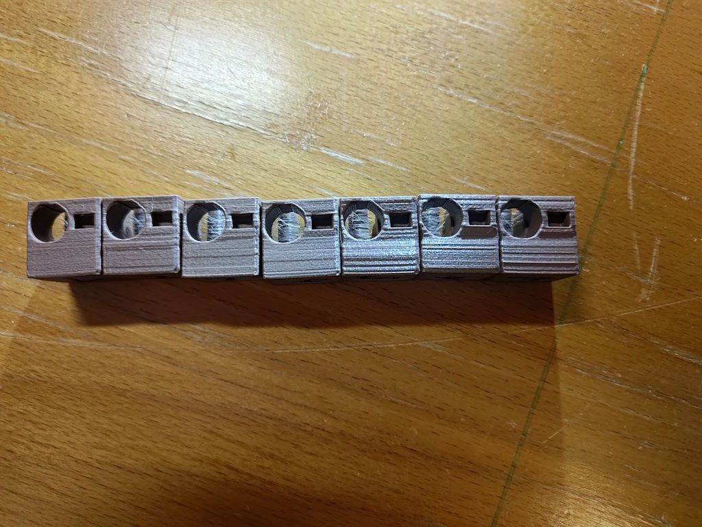
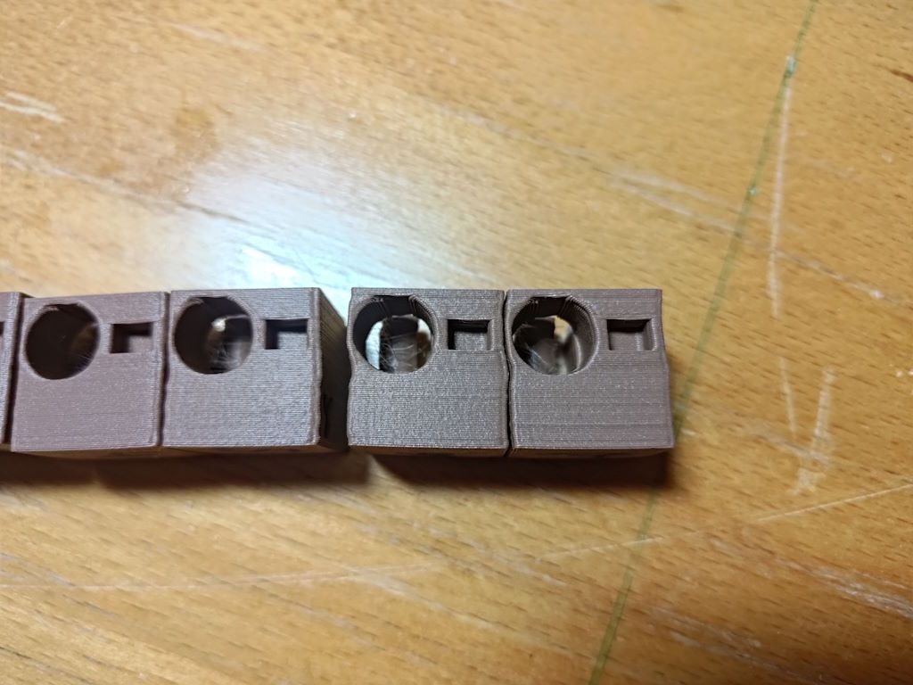
My CoreXY DIY toolchanger is running great with the exception of the integrated JMC stepper servos on X and Y that I tried to get working (again). The problem of gradual layer shifts is shown in the pictures. All the cubes are printed one after the other, same gcode, just different motor parameters (M569 mostly).
A few observations: The leftmost cube was printed with my normal microstepping rate (160 steps/mm), the other ones use the coarsest setting on the motors (20 steps/mm) to highlight the issue. On the second picture you can see that the error is reproducible which rules out random interference. Just increasing the microsteps gets rid of the issue (or rather it doesn't show as much), but the prints are still a lot worse than with stepper motors.
The parameters changes from left to right are:- base line (see attached config.g)
- Microsteps to 20 steps/mm
- Connected shield of step/dir differential signal cable to GND
- Changed M569 T4:8:12:12 to T4:16:12:12
- -> T4:32:32:32
- -> T4:32:8:0
- -> T8:8:8:0
My wild guess is that there might be something wrong with the setting of the direction pin in regards to the step pulses. I tried checking that with the oscilloscope (seperately, not during printing) and it looked like there is ages between a change on the direction pin and the first step pulse. Can't remember the exact number but it was more in the range of milliseconds, not microseconds which is way more than enough. The timing parameters I tried are all well above the minimum stated by the datasheet. I haven't found a way to check the signals during printing, as the connectors don't allow easy access to any pins when connected. I don't think the motor misses any pulses, as that would probably be more random and not reproducible.
Another guess is that the voltage of the differential signals is just barely enough to set a reliable direction signal. The datasheet states a threshold of 3.5V which is edging the 3.6V differential signals of the Expansion Breakout Board (EBB). My gut feeling tells me though that this also should result in more random errors.Hardware and config:
Duet 2 WiFi with Expansion Breakout Board and Duex5, firmware version 3.6 rc1 (also tried with 3.5.4 stable before, no difference)
JMC iHSS60 integrated stepper servos, connected with a shielded cable to differential step/dir interface of driver 8 and 9 on the EBB. Supplied with the same 24V as the Duet and the Duex5. Product page and datasheet: https://www.rocketronics.de/shop/en/jmc-closed-loop-steppermotor-3nm-ihss57-36-30-31.html
In the config there are the lines of gcode for the steppers commented out, as I want to be able to easily revert, if I don't find a solution.; General preferences M575 P1 S1 B57600 ; enable support for PanelDue G90 ; send absolute coordinates... M83 ; ...but relative extruder moves M550 P"Donald Druck" ; set printer name M669 K1 ; select CoreXY mode ; Network ;M552 P"Martin Router King" S1 ; enable network in client mode M552 S1 ; enable networking in client mode M586 P0 S1 ; enable HTTP M586 P1 S0 ; disable FTP M586 P2 S0 ; disable Telnet ; Drives M569 P8 S1 R1 T8:8:8:0 R-1 M569 P9 S1 R1 T8:8:8:0 R-1 ;M569 P2 R-1 ; disable driver 2 (normally Z) M569 P0 S0 ; physical drive 0 (XY1) goes backwards M569 P1 S0 ; physical drive 1 (XY2) goes backwards M569 P2 S1 ; physical drive 2 (Z) goes forwards M569 P3 S1 ; physical drive 3 (B=TC motor) goes forwards M569 P4 S0 ; physical drive 4 (T0 Extruder) goes forwards M569 P5 S0 ; physical drive 5 (T1 Extruder) on Duex5 goes forwards M569 P6 S0 ; physical drive 6 (T2 Extruder) on Duex5 goes forwards ;M584 X0 Y1 Z2 E4:5:6 B3 ; set drive mapping (axes A, B and C are rotational axes) M584 X8 Y9 Z2 E4:5:6 B3 ; set drive mapping (axes A, B and C are rotational axes) M350 X16 Y16 Z16 E16:16 I1 ; configure microstepping with interpolation M350 B8 I0 ; configure microstepping without interpolation M92 X20.00 Y20.00 Z1280.00 E400:562:562 B100 ; set steps per mm (might not work for B, as it is a rotational axis?) M566 X450.00 Y450.00 Z60.00 E300:300:300 B6 ; set maximum instantaneous speed changes (mm/min) M203 X36000.00 Y36000.00 Z1800.00 E3000:3000:3000 B48000 ; set maximum speeds (mm/min). If step losses occur, it might be due to uneven belt tension. M201 X6000.00 Y6000.00 Z300.00 E1200:1200:1200 B12000 ; set accelerations (mm/s^2) ;M906 X1800 Y1800 Z1500 E500:500:500 B400 I100 ; set motor currents (mA) and set idle current to 100% (workaround?) M906 Z1500 E500:500:500 B400 I100 ; set motor currents (mA) and set idle current to 100% (workaround?) ;M84 S0 ; Disable motor idle current reduction ; Axis Limits M208 X0:470 Y0:412 Z0:355 B0:240 S0 ; set axis maxima M564 H0 S1 ; allow movement without homing and inhibit movement outside soft limits (only applies to homed axes) ; Endstops M574 X1 S1 P"xstop" ; configure switch-type (e.g. microswitch) endstop for low end on X via pin xstop M574 Y1 S1 P"!ystop" ; configure switch-type (e.g. microswitch) endstop for low end on Y via pin ystop ;M574 Z1 S1 P"zstop" ; configure switch-type (e.g. microswitch) endstop for low end on Z via pin zstop M574 Z0 P"nil" M574 B1 S3 ; Stall detect TC motor at low end of its range M915 B S3 F1 H400 R0 ; TC motor stall detection configuration ; Z-Probe M558 P5 C"zstop" H3 F300 T36000 ; set Z probe type to switch and the dive height + speeds G31 P500 X0 Y0 Z0 ; set Z probe trigger value, offset and trigger height M557 X40:440 Y20:320 S50 ; define mesh grid ; Heaters M308 S0 P"bedtemp" Y"thermistor" T100000 B4138 ; configure sensor 0 as thermistor on pin bedtemp M950 H0 C"bedheat" T0 ; create bed heater output on bedheat and map it to sensor 0 M307 H0 R0.1 K0.779:0.000 D2.44 E1.35 S1.00 B0 ; Set heating parameters for the bed (PID) M140 H0 ; map heated bed to heater 0 M143 H0 S120 ; set temperature limit for heater 0 to 120C M308 S2 P"e1temp" Y"thermistor" T100000 B4267 ; configure sensor 2 as thermistor on pin e1temp (E3D thermistor cartridge) M950 H1 C"e1heat" T2 ; create nozzle heater output on e1heat and map it to sensor 2 M143 H1 S280 ; set temperature limit for heater 1 to 280C M307 H1 R2.215 K0.251:0.125 D7.51 E1.35 S1.00 B0 V24.3 ; disable bang-bang mode for heater 1 and set heater parameters M308 S3 P"duex.e2temp" Y"thermistor" T100000 B4725 C7.06e-8 ; configure sensor 3 as thermistor on pin e1temp (E3D Revo cartridge) M950 H2 C"duex.e2heat" T3 ; create nozzle heater output on e1heat and map it to sensor 3 M143 H2 S300 ; set temperature limit for heater 2 to 300C M307 H2 R4.287 K0.569:0.000 D2.18 E1.35 S1.00 B0 V24.3 M308 S4 P"duex.e3temp" Y"thermistor" T100000 B4725 C7.06e-8 ; configure sensor 3 as thermistor on pin e1temp (E3D Revo cartridge) M950 H3 C"duex.e3heat" T4 ; create nozzle heater output on e1heat and map it to sensor 3 M143 H3 S300 ; set temperature limit for heater 2 to 300C M307 H3 R3.427 K0.417:0.000 D2.29 E1.35 S1.00 B0 V24.3 ; Fans M950 F1 C"fan0" Q500 ; create fan 1 on pin fan1 and set its frequency M106 P1 S0 H-1 ; set fan 1 value. Thermostatic control is turned off M950 F3 C"duex.fan3" Q500 ; create fan 3 on pin duex.fan3 and set its frequency M106 P3 S0 H-1 ; set fan 3 value. Thermostatic control is turned off M950 F4 C"duex.fan4" Q500 ; create fan 4 on pin duex.fan3 and set its frequency M106 P4 S0 H-1 ; set fan 4 value. Thermostatic control is turned off ; Tools M563 P0 S"LGX FF" D0 H1 F1 ; define tool 0 G10 P0 X2.50 Y49.95 Z-11.0 ; set tool 0 axis offsets G10 P0 R0 S0 ; set initial tool 0 active and standby temperatures to 0C M572 D0 S0.06 ; Configure pressure advance for extruder 0 M563 P1 S"LGX lite 1" D1 H2 F3 ; define tool 1 G10 P1 X-0.05 Y36.7 Z-24.75 ; set tool 1 axis offsets G10 P1 R0 S0 ; set initial tool 1 active and standby temperatures to 0C M572 D1 S0.03 ; Configure pressure advance for extruder 1 M563 P2 S"LGX lite 2" D2 H3 F4 ; define tool 2 G10 P2 X-0.25 Y36.35 Z-24.75 ; set tool 2 axis offsets G10 P2 R0 S0 ; set initial tool 2 active and standby temperatures to 0C M572 D2 S0.03 ; Configure pressure advance for extruder 1 M207 S0.4 F2100 T2100 Z0.2 ; Configure firmware retraction (S=retraction amount, F=retraction feedrate, T=unretraction feedrate, Z=Z-hop height) M302 S160 R80 ; Allow extrusion starting from 160°C and retractions already from 80°C ;G29 S1 ; Enable mesh compensation ; Custom settings are not defined ;M955 P0 I65 C"spi.cs2+spi.cs1" ; Configure accelerometer (I21 for mounting on Revo, I06 for mounting on LGX FF)Any help will be greatly appreciated, this is driving me crazy... If more info is needed I'll happily provide.
Have a lovely evening or rest of your day!")
-
@Eumldeuml try changing the "Activated edge setting" on the driver. There is an error in the manual pages 13/14 so it isn't entirely clear whether SW5 or SW6 selects this (the other one reverses the direction).
M569 setting T2.5:2.5:6:0 should be sufficient for that driver.
Duet WiFi hardware designer and firmware engineer
Please do not ask me for Duet support via PM or email, use the forum
http://www.escher3d.com, https://miscsolutions.wordpress.com -
@dc42 Changing SW5 didn't make a difference sadly.
I did find out though that the motors do sound very crunchy in some manual jogging moves when setting M569 T3:3:6:0. They also lose steps or rather they don't get transmitted correctly as the servo's encoders are hopefully doing their job. The toolhead crashed when trying to pick up a tool right after homing.
The documentation on connecting external stepper motors states that for long cables or cables with high capacitance one should increase the timing values, that's why I tried on going higher with those values. There might be something to that, as witnessed by the motors losing their intended position when using short timings.That leaves the barely high enough 3.6V signalling voltage as the next possible candidate. As per documentation of the EBB:
"Connecting STEP+ from your driver to +5V, which is available on the H6_PWM and/or H7_PWM pin headers (see wiring diagram above), and STEP- for your driver to STEP- on the expansion board"
If I understand correctly, this means there won't be any direct connection from STEP+ on the driver/motor to STEP+ on the EBB? But the signals will still be differential? That doesn't seem to be clear to me. -
@Eumldeuml said in Gradual layer shifts with integrated JMC stepper servos:
If I understand correctly, this means there won't be any direct connection from STEP+ on the driver/motor to STEP+ on the EBB? But the signals will still be differential?
That's correct. Drivers most commonly have opto isolated 5V inputs, which don't require differential drive. A few have RS422-compatible differential inputs; 3V drive is sufficient for those.
Duet WiFi hardware designer and firmware engineer
Please do not ask me for Duet support via PM or email, use the forum
http://www.escher3d.com, https://miscsolutions.wordpress.com -
I did manage to try the 5V signalling but it also didn't make any difference. That was the last lead and I don't really know what I could try next, which is very frustrating. Other people are using JMCs as well so it should work...
There might be something wrong with the motors internally but I don't have the money to just buy new ones without really knowing if they are indeed the problem...@dc42 Can you think of anything else to try? If not I still want to thank you for your input and your support in this forum
-
@Eumldeuml It's always worth checking for mechanical issues. Random shifts that then move back in line are often loose belt pulleys on the motor shaft. As it's a coreXY, but shifts appear in both X and Y direction, it could one pulley that's doing all the moving.
You also seem to have both R1 and R-1 in your M569 commands, which sets the drive enable polarity:
M569 P8 S1 R1 T8:8:8:0 R-1
M569 P9 S1 R1 T8:8:8:0 R-1
Your low number of steps per mm, of 20, for X and Y probably won't be helping accuracy.
Ian
Bed-slinger - Mini5+ WiFi/1LC | RRP Fisher v1 - D2 WiFi | Polargraph - D2 WiFi | TronXY X5S - 6HC/Roto | CNC router - 6HC | Tractus3D T1250 - D2 Eth
-
@droftarts Yes, the steps/mm are quite low. I did that temporarily to highlight the issue and to find a clue faster.
Mechanical issues are most certainly not the root cause, as I checked everything when installing the motors. Good hint though that it might be just one of the motors that has an issue as this will influence movements in both X and Y. Still not sure on how to diagnose this any further. While changing from steppers to the servos I did try to make a few moves with one servo and one stepper but that threw the stepper off almost instantly.The R-1 is for silencing these annoying popups about one stepper motor not being connected properly (out of phase or something). I mean, there isn't even a stepper connected. Those popups are appearing anyway, with or without R-1.
-
@Eumldeuml try setting the motor currents for X and Y to 0. That should get rid of those messages without suppressing them
-
Thank you all for your answers and your tips, even though I couldn't find a solution after hours of tinkering. That's why I admitted defeat and ordered new, better suited stepper motors. The old ones were 0.9° motors with sub-optimal parameters (according to the EMF calculator) which gave me a lot of reliability issues, mainly random unpredictable step losses. For this reason I wanted to upgrade to the JMC servos that I had lying around anyway, just to open another can of worms

Live and learn I guess... Thanky anyway!