smart effector
-
my pin scheme is different from yours, and I have already tried the M558 command that you share, but when I do the G30 the printer goes up instead of down. what I put in was returned to me by the rrf configurator
I noticed there was an error in the RRF configuration tool, it has been fixed so it gives the option of 'zprobe.mod' as the modulation pin for smart effector for Duet 2 WiFi.
in fact I noticed that there are two different wifi duet schemes on the network. I checked on the duet site and indeed it is the same as yours. now I will try to change the order of the wires and I will write the result here. for now thanks for the precious help
You should be using this wiring diagram: https://docs.duet3d.com/Duet3D_hardware/Duet_2_family/Duet_2_WiFi_Ethernet_Hardware_Overview#wiring-diagram
The only other Duet 2 WiFi wiring diagram is for prototype boards (which have a white PCB), which you don't have. It says this very clearly on that wiring diagram. We deliberately made that wiring diagram difficult to find! Yes, the probe header is wired the other way around on that one, but it was changed in 2016!@droftarts you are right, I reversed the wires and the light turns on. now I will do the tests with G31 and then with G30.
then I still have the problem of the print cooling fan that always remains on
thanks for the precious help I will update on the resultsGood, that is progress.
Please can you show how you have wired the cooling fan, on the Duet and on the SmartEffector. In your config.g, you have configured it to be connected to the fan0 on the Duet:
; Fans
M950 F0 C"fan0" ; create fan #0
M106 P0 S0 L0 X1 B0.1 ; configure fan #0
Make sure the wires are plugged into fan0 on the Duet, which is the middle one of the five fan outputs:

fan0 on the Duet should be wired to the PF+ and PF- pins on the 2 x 3 pin black Molex Microfit 3 connector on the top of the SmartEffector. The fan should be plugged in on the bottom of the SmartEffector, to the print cooling fan header.
Make sure that the wires are correctly orientated for V+ and GND in each connector. Reversing the fan may cause the MOSFET that controls it to fail.
Ian
Bed-slinger - Mini5+ WiFi/1LC | RRP Fisher v1 - D2 WiFi | Polargraph - D2 WiFi | TronXY X5S - 6HC/Roto | CNC router - 6HC | Tractus3D T1250 - D2 Eth
-
-
@droftarts ho riacceso la stampante ora e la fan 0 ora rimane spenta. sembra tutto ok. un sincero grazie di cuore per l'aiuto, senza non ne sarei mai uscito.
-
@droftarts said in smart effector:
Ho notato che c'era un errore nello strumento di configurazione RRF, è stato risolto in modo da dare l'opzione di 'zprobe.mod' come pin di modulazione per l'effettore intelligente per Duet 2 WiFi.
devo ricaricare il mio firmware sul configuratore e modificare il parametro "porta di modulazione" da nessuno a "zprobe.mod"?
-
do i need to reload my firmware on the configurator and change the "modulation port" parameter from none to "zprobe.mod"?
You can, but unless you are going to output the set of configuration files again, you don't need to. Make sure to backup the configuration files from the Duet SD card occasionally, especially as you tune the speeds and accelerations.
Ian
Bed-slinger - Mini5+ WiFi/1LC | RRP Fisher v1 - D2 WiFi | Polargraph - D2 WiFi | TronXY X5S - 6HC/Roto | CNC router - 6HC | Tractus3D T1250 - D2 Eth
-
@droftarts non capisco il perchè ma ho acceso oggi la stampante ed il problema della ventola è ritornato
-
@droftarts ho controllato e ricontrollato i cablaggi ma la ventola fan0 rimane sempre accesa. Ho comunque provato ad invertire i fili e la ventola non parte più nemmeno quando richiesto
-
I don't understand why but I turned on the printer today and the fan problem returned
I checked and rechecked the wiring but the fan0 fan always stays on. However I tried to reverse the wires and the fan no longer starts even when requested
Unfortunately, wiring a fan backwards is bad. See https://docs.duet3d.com/User_manual/Connecting_hardware/Fans_connecting#connecting-fans
CAUTION!
Fans are polarised. When connecting a fan to a fan connector, the fan's positive wire (usually red) must be connected to the positive pin of that connector, usually marked V_OUT+ or V_FAN+. The fan's negative wire (normally black) must be connected to the negative pin if it is a PWM controlled fan connector, usually marked out[n]- or FAN[N]-, or the GND pin if it is an always-on fan connector.
If you connect the fan the wrong way round, you may damage the fan, the Duet, or both.It's possible just the MOSFET has failed. Maybe it wasn't working properly anyway. You have a spare connector (FAN2), so you could plug the fan into that, the correct way around, and change your config.g to use that pin.
However, I notice your Duet 2 board has a black PCB. This is a clone board, not produced by Duet3D. We don't support that.
Ian
Bed-slinger - Mini5+ WiFi/1LC | RRP Fisher v1 - D2 WiFi | Polargraph - D2 WiFi | TronXY X5S - 6HC/Roto | CNC router - 6HC | Tractus3D T1250 - D2 Eth
-
@droftarts lo smart effector è originale duet ed il problema sta li. la scheda era su di un'altra stampante e non ha mai avuto problemi
-
@droftarts avevi regione su fan 2 tuto funziona. grazie di tutto il supporto
-
the smart effector is original duet and the problem is there. the card was on another printer and never had problems
I think the fan0 connector failed because you wired the fan backwards. If you want to fix it, try replacing the MOSFET. See https://docs.duet3d.com/en/User_manual/Troubleshooting/Parts#fan-mosfet
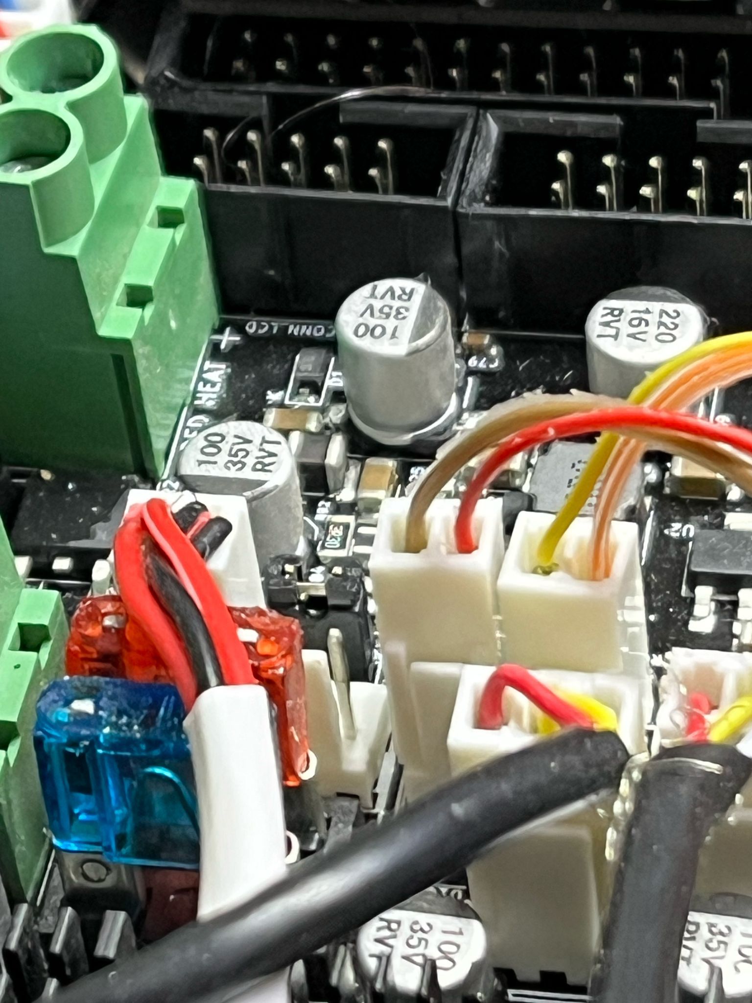
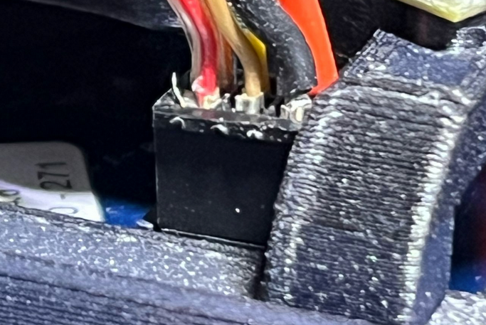
I think you should also check the plug on the Smart Effector that connects to the Duet 2 board. These pins look like they are not fully inserted into the housing. There also looks like there might be some wires poking out, that may cause a short.
you had region on fan 2 everything works. thanks for all the support
Great, glad you got it working. Please check the above.
Ian