Duet3D Logo Duet3D
    • Tags
    • Documentation
    • Order
    • Register
    • Login

    Laser wiring?

    Scheduled Pinned Locked Moved
    Duet Hardware and wiring
    6
    26
    5.5k
    Loading More Posts
    • Oldest to Newest
    • Newest to Oldest
    • Most Votes
    Reply
    • Reply as topic
    Log in to reply
    This topic has been deleted. Only users with topic management privileges can see it.
    • flippnswitchezundefined
      flippnswitchez
      last edited by

      Thank you, Sir!!

      Tronxy X5S w? DuetWifi
      CTC

      1 Reply Last reply Reply Quote 0
      • nirmal005undefined
        nirmal005
        last edited by

        Hi,

        I am new to 3D printing, so please forgive my ignorance.

        I am planning to buy DuetWiFi so that I can connect a 12v 15W 450nm TTL controlled laster module. The answer to this exact question is what I am looking for.

        @flippnswitchez, Were you able to make it work? If yes, would you please share your circuit schematics? It would be really helpful to know what needs to be connected where.

        flippnswitchezundefined 1 Reply Last reply Reply Quote 0
        • flippnswitchezundefined
          flippnswitchez @nirmal005
          last edited by

          @nirmal005 I was sidetracked and have not finished yet, but yes it should work. I was sidetracked by some troubles getting my printer back up and working from the switch between boards. I also added a 24v power supply because of my bed, so I also had to order a step-down module for the laser.

          Tronxy X5S w? DuetWifi
          CTC

          1 Reply Last reply Reply Quote 0
          • keyz182undefined
            keyz182
            last edited by

            @dc42 said in Laser wiring?:

            The heater pins on the expansion are active low, so you will get a glitch turning the laser on while the Duet initialises itself. I suggest you do the same as we do for the heater mosfet drive circuits, which is to use a 74HCT02 gate powered from 5V to gate the signal with +3.3V, and invert it and level shift it to 5V.

            How would I go about wiring this configuration up? I have a laser module that takes a 5v PWM signal that I'd like to get hooked up.

            1 Reply Last reply Reply Quote 0
            • resamundefined
              resam
              last edited by

              Take a 74HCT02 (or some other form of NAND/NOR/inverter logic gate), and feed in your control signal from the Duet. The output of the logic gate then goes to the 5V-PMW input of the laser.

              A typical 74HCT02 (Quad 2-input NOR gate) gets connected to +5V and GND.
              1A and 1B get connected together and then to your Duet output pin.
              1Y goes to the 5V-PWM laser input.
              (as the 74HCT02 as 4 such logic gates, you can also use 2A+2B with 2Y, 3A+3B with 3Y, etc.)
              Just look up the pin assignment in the 74HCT02 datasheet (e.g., https://assets.nexperia.com/documents/data-sheet/74HC_HCT02.pdf on page 2)

              1 Reply Last reply Reply Quote 0
              • keyz182undefined
                keyz182
                last edited by

                @resam thanks 🙂

                I wasn't sure how to wire up the 1a,b inputs, but you've cleared that up for me!

                1 Reply Last reply Reply Quote 0
                • keyz182undefined
                  keyz182
                  last edited by

                  0_1530960731068_Schematic_laserpwmduet_Sheet-1_20180707115047.png

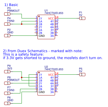
                  Does #1 in the image look correct? Also, would #2 work? It was taken from the power mosfet drivers from the Duex boards (there's also a cap between 5V and GND I missed out).

                  I tried #2, because I figured but it seems the laser off on 0 and 100%, and on full everywhere between.

                  I can try #1, but want to make sure it's correct this time before wiring it up.

                  1 Reply Last reply Reply Quote 0
                  • resamundefined
                    resam
                    last edited by

                    I'm using #1, but with the HEATER_3 pin, if I remember correctly.
                    Not sure how FAN2- behaves in this circuit...

                    keyz182undefined 1 Reply Last reply Reply Quote 0
                    • keyz182undefined
                      keyz182 @resam
                      last edited by

                      @resam D'oh, Looks like I got turned around - Will try on heater now.

                      1 Reply Last reply Reply Quote 0
                      • resamundefined
                        resam
                        last edited by

                        On my system:

                        M452 P3 to enable "laser mode" on heater 3.
                        M3 S1 turn on the laser at the lowest intensity.
                        M3 S255 at full intensity.
                        M5 and M3 S0 is laser off.

                        1 Reply Last reply Reply Quote 0
                        • keyz182undefined
                          keyz182
                          last edited by

                          It works! I think I'm going to have to write this up later and put it up here/on the wiki for others to reference. @dc42 is there any downside to using circuit #2 in my previous reply above vs the "simpler" one? If not, I'll stick with #2.

                          @resam said in Laser wiring?:

                          On my system:

                          M452 P3 to enable "laser mode" on heater 3.
                          M3 S1 turn on the laser at the lowest intensity.
                          M3 S255 at full intensity.
                          M5 and M3 S0 is laser off.

                          Yup, that's what I've got now 🙂

                          1 Reply Last reply Reply Quote 0
                          • dc42undefined
                            dc42 administrators
                            last edited by

                            We use circuit #2 In the heater wiring, because users occasionally short +3.3V to ground because of incorrect endstop wiring or other reasons, and when that happens we don't want all the heaters to turn on at full power. The same considerations apply to a laser, so I suggest circuit #2.

                            Duet WiFi hardware designer and firmware engineer
                            Please do not ask me for Duet support via PM or email, use the forum
                            http://www.escher3d.com, https://miscsolutions.wordpress.com

                            keyz182undefined 1 Reply Last reply Reply Quote 0
                            • keyz182undefined
                              keyz182 @dc42
                              last edited by

                              @dc42 Great, that's what I went with, and it works 🙂

                              Thanks all for the help. I've got a bunch of cable management to do today, and once that's done, the real testing will begin. If the tests all work, I'll write it up and post it here for some vetting, and if it looks good, I (or someone) can put it up on the wifi 🙂

                              1 Reply Last reply Reply Quote 1
                              • keyz182undefined
                                keyz182
                                last edited by

                                Prepping the documentation here - https://gist.github.com/keyz182/34601ec4ba4a19c55a177d0d1738d5a3

                                Any notes or corrections welcome. Once done and peer-reviewed I'll get it moved to the wiki.

                                1 Reply Last reply Reply Quote 0
                                • resamundefined
                                  resam
                                  last edited by

                                  Nice!

                                  I think you got the GND and V_IN connection mixed up on the LASER_OUT header...?

                                  keyz182undefined 1 Reply Last reply Reply Quote 0
                                  • keyz182undefined
                                    keyz182 @resam
                                    last edited by

                                    @resam Good catch, fixed 🙂

                                    1 Reply Last reply Reply Quote 0
                                    • keyz182undefined
                                      keyz182
                                      last edited by

                                      Just realised I selected the 74HCT02D, rather than the 74HCT02. It's datasheet claims it's both TTL and CMOS compatible.

                                      I ordered a few boards from JLPCB because I've never done board design before, and figured this would be a good start.

                                      I think it should work, as the output is dependent on VCC rather than anything else, and other than also having CMOS input compatibility, it seems the same. Can someone with more knowledge in electronic weigh in to say if it's a choice that'll work, or if I need to change it?

                                      T3P3Tonyundefined 1 Reply Last reply Reply Quote 0
                                      • T3P3Tonyundefined
                                        T3P3Tony administrators @keyz182
                                        last edited by T3P3Tony

                                        @keyz182 said in Laser wiring?:8

                                        74HCT02D

                                        should be fine, the datasheet shows the "D" to mean its SIOC foot print. What determines the logic levels is the HC/HCT (74HC02 vs 74HCT02)

                                        https://en.wikipedia.org/wiki/7400_series#7400_series_derivative_families

                                        www.duet3d.com

                                        keyz182undefined 1 Reply Last reply Reply Quote 0
                                        • keyz182undefined
                                          keyz182 @T3P3Tony
                                          last edited by

                                          @t3p3tony Awesome, thanks.

                                          Do you think the "Circuit operational theory" section I just added looks correct? I want to make sure people are able to understand why they're doing something, not just that they should do it.

                                          https://gist.github.com/keyz182/34601ec4ba4a19c55a177d0d1738d5a3

                                          T3P3Tonyundefined 1 Reply Last reply Reply Quote 0
                                          • T3P3Tonyundefined
                                            T3P3Tony administrators @keyz182
                                            last edited by

                                            by connecting the heater PWM to two input pins of the 74HCT02, we get an inversion of the PWM, such that when PWM out is pulled low, the 74HCT02 output is driven high.

                                            This is a little confusing as written because the diagram shows PWM connected to only one input. maybe re-order the text so it is clear what the 3.3V is doing first?

                                            www.duet3d.com

                                            keyz182undefined 1 Reply Last reply Reply Quote 0
                                            • First post
                                              Last post
                                            Unless otherwise noted, all forum content is licensed under CC-BY-SA