effector tilting into bed on print
-
Hi:
I have a delta that I had problems with for a while, but with the great help I got here, it was sorted out.One day, about a month age, when I went to print, my effector started lowering toward the x pillar until it dug into the bed and I had to power off.
I discovered that a pair of the fish eye ends had separated from the aluminum rods and would just slide off.
I have replaced the rods with magnetic versions and while they are much longer, I have reset the printer. My bed leveling is just about spot on when I trigger at each point in the bed.g file.
The effector lightly touches a piece of paper at Z=0.
I thought I had everything set perfectly.
My effector still wants to head downhill toward the X pillar. I can't see why.
Also, Auto Calibration doesn't seem to make any changes.
Suggestions?Config.g
; Configuration file for Duet WiFi (firmware version 1.20 or newer)
; executed by the firmware on start-up
;
; generated by RepRapFirmware Configuration Tool on Wed Jun 13 2018 16:33:57 GMT-0400 (Eastern Daylight Time); General preferences
G90 ; Send absolute coordinates...
M83 ; ...but relative extruder moves;*** The homed height is deliberately set too high in the following - you will adjust it during calibration.
M665 R103 L360.20 B85 H203 ; Set delta radius, diagonal rod length, printable radius and homed height
M666 X0 Y0 Z0 ; Put your endstop adjustments here, or let auto calibration find them; Network
M550 PMiniKossel ; Set machine name
M552 S1 ; Enable network
M587 S"BELL137" P"DAAE9D3D996E" I192.168.1.14 J192.168.1.254 K255.255.255.0 ; Configure access point and IP addresses. You can delete this line once connected
M586 P0 S1 ; Enable HTTP
M586 P1 S0 ; Disable FTP
M586 P2 S0 ; Disable Telnet; Drives
M569 P0 S1 ; Drive 0 goes forwards
M569 P1 S1 ; Drive 1 goes forwards
M569 P2 S1 ; Drive 2 goes forwards
M569 P3 S0 ; Drive 3 goes backwards
M350 X16 Y16 Z16 E16 I0 ; Configure microstepping without interpolation
M92 X80 Y80 Z80 E663 ; Set steps per mm
M566 X1200 Y1200 Z1200 E1200 ; Set maximum instantaneous speed changes (mm/min)
M203 X18000 Y18000 Z18000 E1200 ; Set maximum speeds (mm/min)
M201 X1000 Y1000 Z1000 E1000 ; Set accelerations (mm/s^2)
M906 X1000 Y1000 Z1000 E800 I30 ; Set motor currents (mA) and motor idle factor in per cent
M84 S30 ; Set idle timeout; Axis Limits
M208 Z-0.1 S1 ; Set minimum Z; Endstops
M574 X2 Y2 Z2 S1 ; Set active high endstops; Z-Probe
M558 P4 H10 F120 T2400 I1 ; Set Z probe type to unmodulated and the dive height + speeds
G31 P500 X11 Y0 Z-1.159 ; Set Z probe trigger value, offset and trigger height
M557 R80 S20 ; Define mesh grid; Heaters
M307 H0 B0 S1.00 ; Disable bang-bang mode for the bed heater and set PWM limit
M305 P0 T100000 B3950 C0 R4700 ; Set thermistor + ADC parameters for heater 0
M143 H0 S120 ; Set temperature limit for heater 0 to 120C
M305 P1 T100000 B4388 C0 R4700 ; Set thermistor + ADC parameters for heater 1
M143 H1 S280 ; Set temperature limit for heater 1 to 280C; Fans
M106 P0 S0 I0 F500 H-1 ; Set fan 0 value, PWM signal inversion and frequency. Thermostatic control is turned off
M106 P1 S0 I0 F500 H-1 ; Set fan 1 value, PWM signal inversion and frequency. Thermostatic control is turned off
M106 P2 S1 I0 F500 H1 T45 ; Set fan 2 value, PWM signal inversion and frequency. Thermostatic control is turned on; Tools
M563 P0 D0 H1 ; Define tool 0
G10 P0 X0 Y0 Z0 ; Set tool 0 axis offsets
G10 P0 R0 S0 ; Set initial tool 0 active and standby temperatures to 0C; Automatic power saving
M911 S10 R11 P"M913 X0 Y0 G91 M83 G1 Z3 E-5 F1000" ; Set voltage thresholds and actions to run on power loss; Custom settings are not configured
; Miscellaneous
T0 ; Select first tool
M501 -
Basic confirmation: A pair of rods, "pair" meaning the two rods coming from a single tower carriage, each "pair" of rods joins the LONG side of the effector, and NOT the balls that are "close together on a corner", correct?
This is a super-basic thing... but I've gotten it wrong before when removing and re-installing an effector!!
")
Also, if it is wrong, the effector can be "sloppy moved" around, meaning it tilts as it moves, and it moves a few inches/centimeters with NO movement of the towers.
So... check that first. Rod pair from a carriage to LONG side of effector.
-
Next question, may seem like a duplicate of above, but is slightly different, and another way of checking mechanics.
With printer POWERED OFF, can you move effector, at about mid height of total effector Z travel, can you move effector smoothly in from center toward each tower a little, and do the carriages move as you'd expect, namely the carriage on the tower you are moving toward moves UP a lot, and the other two move down a little? Check all three...
Does that check pass? Again, this is verifying mechanics before looking at config.
Delta / Kossel printer fanatic
-
Your config.g contains
M665 R103 L360.20 B85 H203 ; Set delta radius, diagonal rod length, printable radius and homed heightPlease take this with a "Grain of Salt", because I am not a MiniKossel owner...
From what I've seen on those printers, the L value looks high. From the center of a ball to the center of a ball, they are 360.20? And/or if you got them from Haydn Huntley (or Blue Eagle Labs, same thing), that's what the label on the rods says?
I did catch that you said "the rods are long" and so this may be correct.
Also, over-long rods actually IMPROVE geometry and accuracy in a Delta, they just cost a little maximum Z.
Delta / Kossel printer fanatic
-
AND!!!
config.g ends with M501. Which loads config-override.g. What is in that file?
-
Hi Danal:
I got caught on that one when I first put it together, but something made me look at it again, so I did move them to the LONG side.
Thanks. That was a good thing to think of.
Tim -
@danal
Hi:
I can move the carriage to each tower with no problem. The movement is what I would expect.
thanks,
Tim -
@danal
That's great news that longer rods improve geometry. There is a label on each one. 4 say 360.20 and 2 say 360.21. I put the two that say .21 on the same pulley arm.
I'm not worried about Z height. I have a cartesian that I built for the big stuff.
Tim -
@timvukman
Here is the config override; This is a system-generated file - do not edit
; Delta parameters
M665 L360.200 R103.000 H203.000 B85.0 X0.000 Y0.000 Z0.000
M666 X0.000 Y0.000 Z0.000 A0.00 B0.00
; Heater model parameters
M307 H0 A90.0 C700.0 D10.0 S1.00 V0.0 B0
M307 H1 A340.0 C140.0 D5.5 S1.00 V0.0 B0
M307 H2 A340.0 C140.0 D5.5 S1.00 V0.0 B0
M307 H3 A340.0 C140.0 D5.5 S1.00 V0.0 B0
M307 H4 A340.0 C140.0 D5.5 S1.00 V0.0 B0
M307 H5 A340.0 C140.0 D5.5 S1.00 V0.0 B0
M307 H6 A340.0 C140.0 D5.5 S1.00 V0.0 B0
M307 H7 A340.0 C140.0 D5.5 S1.00 V0.0 B0 -
OK, good mechanical checks.
And, I'm not catching anything in the config files on first look.
I will keep looking.
-
Ok,
Thanks -
Hi:
Still stuck....... At one point I was able to create a graph showing the data from the auto calibrate. There was a definite low on the left and high on the right. I have not been able to recreate the graph.
-
@timvukman you can see the stored map by choosing show mech grid heightmap:
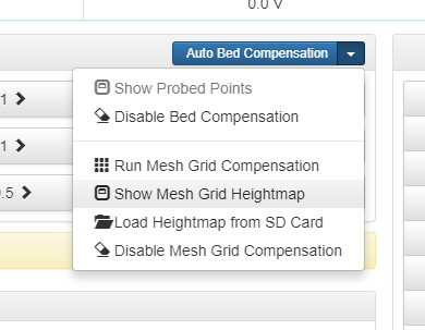
this picture is a cartesian however it should be in the same place on a delta.
See the full documentation for DWC here:
https://duet3d.dozuki.com/Wiki/Duet_Web_Control_Manual#Section_Probing_the_Bed
-
Thanks T3P3Tony.
I was trying to load the heightmap from the SD Card.
Tim -
@timvukman said in effector tilting into bed on print:
Hi:
Still stuck.......
How is it going?
Is it possible to video the effector during a G32 probe sequence?
-
@danal
Hi:
Unfortunately, it's not going anywhere.
 image url)I believe I had read about offsetting the values that create the bed level map. I was under the impression that "Auto Delta Configuration" was supposed to make the changes (I presume in the conf or override files) by itself, whether that is to adjust the diagonal length, or radius, etc.
I have selected auto delta config several times, and it goes through the process, but nothing ever changes. I just want to know if I am doing something wrong, or if it is not implemented.
Thanks
Tim -
@timvukman said in effector tilting into bed on print:
@danal
I was under the impression that "Auto Delta Configuration" was supposed to make the changes (I presume in the conf or override files) by itself, whether that is to adjust the diagonal length, or radius, etc.Auto Delta Config (which is the same as issuing G32) updates different things depending on the contents of the bed.g file. In particular the last G30 in bed.g will have an S parameter.
There are a lot of choices, but I tend to use S6 or S8 on Delta Printers. More info here:
https://duet3d.dozuki.com/Wiki/Calibrating_a_delta_printer#Section_Setting_up_the_bed_g_file
-
And, G32 does work (assuming no error messages), but it does NOT save its results across power cycles (and/or reboots). To save the results, issue:
M500
Also, the saved results must be reloaded. In your 'config.g', place an M501 somewhere near the end of the file.
.
By the way, you can look at what it saved. M500 really writes a file called "config-override.g". M501 reads that same file. You can look in that file with the system editor. When calibrating, your primary interest will be to compare the M665 command in 'config-override.g' vs. the one in 'config.g'.
-
And, last, the map you are showing is from mesh bed leveling. Get CALIBRATION (G32) working to your satisfaction before you mess with leveling...
-
Hi Danal
I have run auto config (g32) many times. ( and did an M500, then power cycled the printer)Should I be running it in stages, ie a different value of S in bed.g starting at 4 and working up?
I did some manual adjustments in bed.g - H value, based on probing each point individually subtracting the center point result from the returned result.
My observation is that I sent the G0 with x and y values, which the printer moved to. When I issue the G30 S-1, the effector moved to center from where it was after the G0, and then probes there.
It was my understanding that the process I needed to follow was to determine the trigger height at center, including a sheet of paper and then set that as the 0 value for Z From there, the documentation directs you to adjusting the heights of the probing points in the bed.g file.
The only changes I have ever seen in the config.g.bak file are the height values that I manually added by putting them in there when G32 did not edit the file.
I have followed the Auto Calibration instructions to the letter. G32 does nothing.
I have run M665 and M666 without parameters and I get the values that are in my config.g file. M666 returns 0 across the board as the adjustments made.I got onto the bed mesh map hoping that it would show me the changes as a visual.
It would appear to me then, that the issue is getting G32 to work.
While G32 is running, I get no feedback from the software interface. No coordinates change values, and nothing pops up on the screen to indicate any values when the bed is probed.
What steps can I take to find out what is going on?
Thanks
Tim