effector tilting into bed on print
-
Hi:
I have now received and installed the aluminum corners for my printer. The lower ones are single thick pieces and the upper ones are the normal single thickness.
I had hoped that I had some sort of gap in the old plastic parts causing my issues. With the aluminum, everything is tight!
Auto Configuration is returning
G32
Calibrated 6 factors using 10 points, deviation before 0.071 after 0.066
5:32:20 PMG32
Calibrated 6 factors using 10 points, deviation before 0.075 after 0.067
2:02:38 PMG32
Calibrated 6 factors using 10 points, deviation before 0.071 after 0.058
I am surprised that these numbers are changing. I would have expected that they would settle out and then stay the same each time.I did try to print, which was not a good idea. I am not printing at the center of the bed, and the print height is not steady.
All ideas welcome
-
The numbers change because the bed probe reading heights you are getting are varying by about 0.01mm. This is a very small amount, comparable with the size of a single 1/16 microstep if your delta printer uses 1.8deg motors.
If you are using M558 P5 with your Smart Effector, you may get slightly better results with M558 P8.
Although your calibration deviation is not as low as many users obtain, it should be good enough to print with. I used to print with a calibration deviation of 0.12mm before I upgraded my delta to linear rails and Smart Effector.
-
@timvukman Just to re-iterate what dc42 said, those figures are good enough to print with. It's unlikely that you can see such a deviation with the naked eye, so something else must be going on.
I wonder if you have an old mesh bed compensation file that's being loaded at startup. Running G29 S2 will clear a pre-existing mesh.
It might also be a good idea to post your config.g, config-override.g and bed.g files.
adavidm
-
@dc42. thanks for discussing the bed probe heights. I feel better about that now. I will try the M558 P8.
@adavidm I will clear the bed compensation file with G29 S2. The deviation that I am talking about is that the print started high in that it was not putting down filament. I was printing a configuration cube, and what I was getting was not cube shaped. The right rear corner seemed like it was following a radius, although I was well within my bed printing area.
The nozzle did dig into the masking tape at one point which I don't understand.; Configuration file for Duet WiFi (firmware version 1.20 or newer)
; executed by the firmware on start-up
;
; generated by RepRapFirmware Configuration Tool on Wed Jun 13 2018 16:33:57 GMT-0400 (Eastern Daylight Time); General preferences
G90 ; Send absolute coordinates...
M83 ; ...but relative extruder moves;*** The homed height is deliberately set too high in the following - you will adjust it during calibration.
M665 R80 L360.20 B80 H161.59 ; Set delta radius, diagonal rod length, printable radius and homed height
M666 X0 Y0 Z0 ; Put your endstop adjustments here, or let auto calibration find them; Network
M550 PMiniKossel ; Set machine name
M552 S1 ; Enable network
M587 S"BELL137" P"DAAE9D3D996E" I192.168.1.14 J192.168.1.254 K255.255.255.0 ; Configure access point and IP addresses. You can delete this line once connected
M586 P0 S1 ; Enable HTTP
M586 P1 S0 ; Disable FTP
M586 P2 S0 ; Disable Telnet; Drives
M569 P0 S1 ; Drive 0 goes forwards
M569 P1 S1 ; Drive 1 goes forwards
M569 P2 S1 ; Drive 2 goes forwards
M569 P3 S0 ; Drive 3 goes backwards
M350 X16 Y16 Z16 E16 I1 ; Configure microstepping without interpolation
M92 X80 Y80 Z80 E157.5 ; Set steps per mm
M566 X1200 Y1200 Z1200 E1200 ; Set maximum instantaneous speed changes (mm/min)
M203 X18000 Y18000 Z18000 E1200 ; Set maximum speeds (mm/min)
M201 X1000 Y1000 Z1000 E1000 ; Set accelerations (mm/s^2)
M906 X1000 Y1000 Z1000 E800 I30 ; Set motor currents (mA) and motor idle factor in per cent
M84 S30 ; Set idle timeout; Axis Limits
M208 Z-0.1 S1 ; Set minimum Z; Endstops
M574 X2 Y2 Z2 S1 ; Set active high endstops; Z-Probe
M558 P5 R0.4 H20 F1200 ; Set Z probe type to unmodulated and the dive height + speeds
G31 P100 X0 Y0 Z-0.239 ; Set Z probe trigger value, offset and trigger height
M557 R80 S20 ; Define mesh grid; Heaters
M307 H0 B0 S1.00 ; Disable bang-bang mode for the bed heater and set PWM limit
M305 P0 T100000 B3950 C0 R4700 ; Set thermistor + ADC parameters for heater 0
M143 H0 S120 ; Set temperature limit for heater 0 to 120C
M305 P1 T100000 B4388 C0 R4700 ; Set thermistor + ADC parameters for heater 1
M143 H1 S280 ; Set temperature limit for heater 1 to 280C; Fans
M106 P0 S0 I0 F500 H-1 ; Set fan 0 value, PWM signal inversion and frequency. Thermostatic control is turned off
M106 P1 S0 I0 F500 H-1 ; Set fan 1 value, PWM signal inversion and frequency. Thermostatic control is turned off
M106 P2 S1 I0 F500 H1 T45 ; Set fan 2 value, PWM signal inversion and frequency. Thermostatic control is turned on; Tools
M563 P0 D0 H1 ; Define tool 0
G10 P0 X0 Y0 Z0 ; Set tool 0 axis offsets
G10 P0 R0 S0 ; Set initial tool 0 active and standby temperatures to 0C; Automatic power saving
M911 S10 R11 P"M913 X0 Y0 G91 M83 G1 Z3 E-5 F1000" ; Set voltage thresholds and actions to run on power loss; Custom settings are not configured
; Miscellaneous
T0 ; Select first tool
M501; This is a system-generated file - do not edit
; Delta parameters
M665 L360.200 R117.268 H159.487 B85.0 X-1.163 Y-2.244 Z0.000
M666 X0.425 Y3.690 Z-4.114 A0.00 B0.00
; Heater model parameters
M307 H0 A90.0 C700.0 D10.0 S1.00 V0.0 B0
M307 H1 A340.0 C140.0 D5.5 S1.00 V0.0 B0
M307 H2 A340.0 C140.0 D5.5 S1.00 V0.0 B0
M307 H3 A340.0 C140.0 D5.5 S1.00 V0.0 B0
M307 H4 A340.0 C140.0 D5.5 S1.00 V0.0 B0
M307 H5 A340.0 C140.0 D5.5 S1.00 V0.0 B0
M307 H6 A340.0 C140.0 D5.5 S1.00 V0.0 B0
M307 H7 A340.0 C140.0 D5.5 S1.00 V0.0 B0; bed.g file for RepRapFirmware, generated by Escher3D calculator
; 10 points, 6 factors, probing radius: 95, probe offset (0, 0)
G30 P0 X0.00 Y95.00 Z-99999 H0
G30 P1 X82.27 Y47.50 Z-99999 H0
G30 P2 X82.27 Y-47.50 Z-99999 H0
G30 P3 X0.00 Y-95.00 Z-99999 H0
G30 P4 X-82.27 Y-47.50 Z-99999 H0
G30 P5 X-82.27 Y47.50 Z-99999 H0
G30 P6 X0.00 Y47.50 Z-99999 H0
G30 P7 X41.14 Y-23.75 Z-99999 H0
G30 P8 X-41.14 Y-23.75 Z-99999 H0
G30 P9 X0 Y0 Z-99999 S6 -
one thing I notice from those files is that you have your bed set to 85mm radius but you are probing to 95mm are you sure you are actually getting a good probe when your Y hit the 95mm point's?
Doug
-
@Doug1957
Thankyou. I did not spot that.I have set the radius to 95, and rerun the G29 command.
That would explain what the hot end was doing when I printed the configuration cube. It was rounding off the back corner based on my radius of 80.
-
When I try printing an object, the nozzle is digging into the masking tape that I have on the bed.
In simplify3d, I am telling the printer to print at 0.20mm
I have first layer height at 90%
First layer width at 100%I have new rods coming that are shorter than my current rods and metal carriages to replace the plastic ones that are running up and down the vertical pillars.
How critical is belt tension? My belts are not as tight as I would like, but they are not skipping. I can pinch them anywhere along the travel length and the backs of the belts will touch with no real pressure needed. There is certainly no spring pushing back against my fingers.
-
@timvukman said in effector tilting into bed on print:
G31 P100 X0 Y0 Z-0.239 ; Set Z probe trigger value, offset and trigger height
This line is saying that the probe is 0.239mm below the bed when triggered. This seems fairly high for the smart effector and could be causing the digging.
Z-0.1 is the recommended value and works well for me.
It sounds like you are getting there, keep going!
adavidm
-
@adavidm
0.1 is the new numberAnother issue has surfaced. I think my cube model is bad. It really doesn't try to put down a cube. More of a straight line, and then a big move left and another straight light over then, and then a heater fault on the nozzle heater which I have never seen before.
-
It's unlikely the model is at fault. Upload the gcode somewhere for someone to check if you like but I do not think that is the source of your problems.
Have you run PID tuning on the hotend and bed heaters? If not then you should do that now. There are several kinds of heater faults but running PID tuning should be your next step. There are instructions in the documentation.
Once you've got that to work successfully, we can see if the problem persists.
-
I have run the heater PID, but maybe only for the bed. I will run it now.
I have pulled up the gcode for the model I was printing, and there are no obvious faults in the file structure, etc. Everything looks like it is broken into nice clean block for each layer. I ran a file check on it anyway and it was clean.
-
I ran the PID tuning on both heaters
No Faults came up.
As A general question, what do I have to check to make sure that my Simplify3d software is correctly configured for my delta printer.
I have seen situations where the model does not print at or about the center of the bed. I am assuming that it should. The favourite starting position seems to be a little on the high side of what would be X on a cartesian and a little back from center in the Y axis.I am assuming that the hot end will step upward on each layer by the 80mm/step. What should my layer height be in Simplify3d, or will that be automatic based on the printer hardwawre?
6:51:41 PMM500
6:51:14 PMWarning: Heater 1 appears to be over-powered. If left on at full power, its temperature is predicted to reach 515C.Auto tune heater 1 completed in 220 sec
Use M307 H1 to see the result, or M500 to save the result in config-override.g
6:48:59 PMAuto tune phase 3, peak temperature was 209.6
6:48:50 PMAuto tune phase 2, heater off
6:47:40 PMAuto tune phase 1, heater on
6:47:34 PMM303 H1
Auto tuning heater 1 using target temperature 200.0°C and PWM 1.00 - do not leave printer unattended6:46:18 PMAuto tune heater 0 completed in 460 sec
Use M307 H0 to see the result, or M500 to save the result in config-override.g
6:41:29 PMM303 H1
6:41:10 PMAuto tune phase 3, peak temperature was 75.3
6:41:03 PMAuto tune phase 2, heater off
6:38:43 PMAuto tune phase 1, heater on
6:38:38 PMM303 H0
Auto tuning heater 0 using target temperature 75.0°C and PWM 1.00 - do not leave printer unattended -
@timvukman said in effector tilting into bed on print:
No Faults came up.
OK, so have you saved that result into the config-override.g by running M500? Alternatively, you can (and probably should) put the results into the M307 in config.g, the tuning is unlikely to change unless you make hardware changes.
I have seen situations where the model does not print at or about the center of the bed. I am assuming that it should. The favourite starting position seems to be a little on the high side of what would be X on a cartesian and a little back from center in the Y axis.
Can you post a screenshot of the "Machine" tab from the "Tools->Options" menu? Assuming you've set the machine up as a delta in there it should be set forever. If you have the Simplify3D configuration correct then the object will print on the bed in the same location and orientation as the model on screen.
Having said that, your endstop offsets are:
M666 X0.425 Y3.690 Z-4.114 A0.00 B0.00If I were you I'd try and reduce that difference. Someone else can chime in here if I'm wrong but I think the effect of those large compensations will be to move the centre of the coordinate system away from the centre of the bed. Auto calibration can be a good thing, especially on deltas, but you should make every effort to get the system mechanically correct first. In this case, when the carriages trigger the endstops, they should be at the same height above the bed from each other. Depending on the kind of endstop and/or carriage you have fitted, the method of adjustment will be different. Post a photo if you are not sure. You should be able to get to better than 1mm deviation between endstops without too much effort.
I am assuming that the hot end will step upward on each layer by the 80mm/step. What should my layer height be in Simplify3d, or will that be automatic based on the printer hardwawre?
The layer height you choose varies based on lots of parameters but it's basically a tradeoff between speed and z-resolution. For now, and assuming you are using a 0.5 or 0.6mm nozzle, I'd use something like 0.2 or 0.3mm layer height.
-
This is the result from the PID tuning of the heaters
; Heater model parameters
M307 H0 A129.5 C334.4 D0.5 S1.00 V12.1 B0
M307 H1 A490.4 C147.5 D5.4 S1.00 V12.3 B0The heater section from my config.g file is
; Heaters
M307 H0 B0 S1.00 ; Disable bang-bang mode for the bed heater and set PWM limit
M305 P0 T100000 B3950 C0 R4700 ; Set thermistor + ADC parameters for heater 0
M143 H0 S120 ; Set temperature limit for heater 0 to 120C
M305 P1 T100000 B4388 C0 R4700 ; Set thermistor + ADC parameters for heater 1
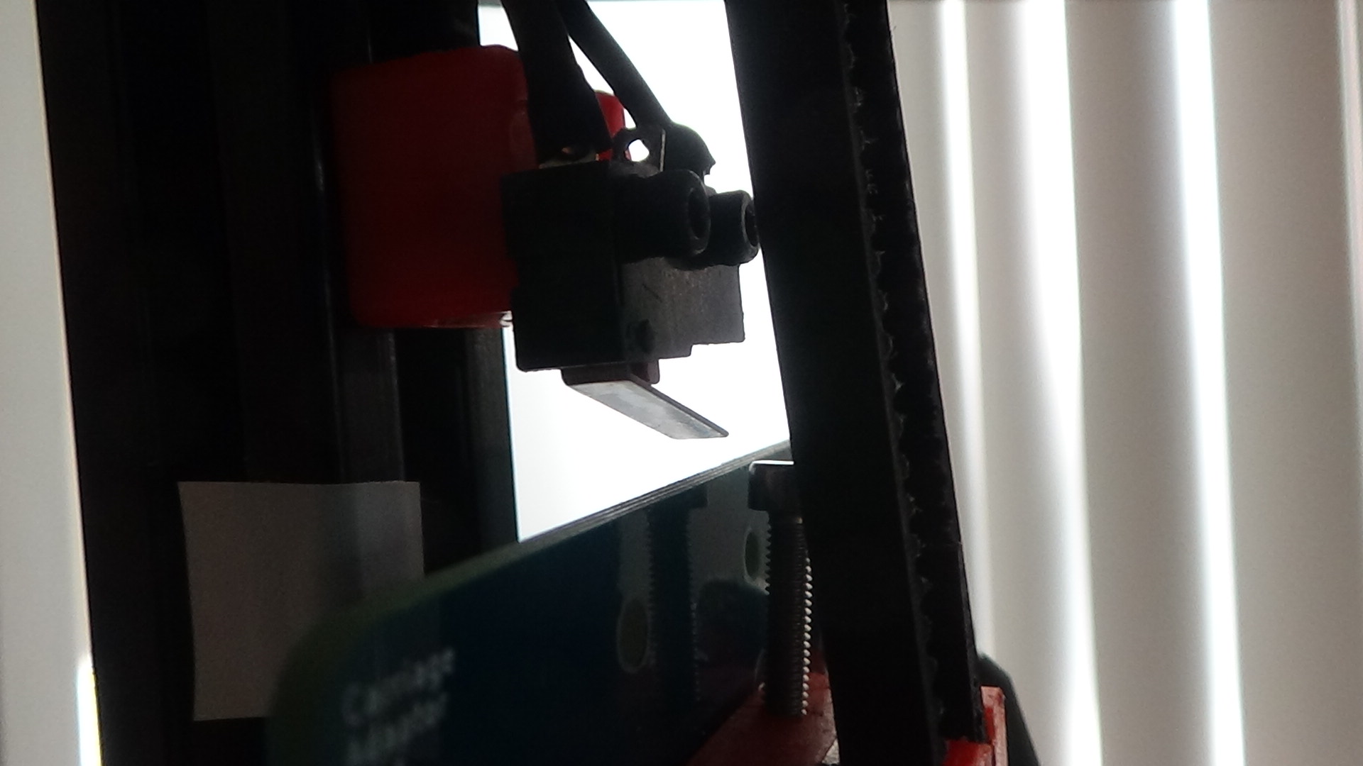
M143 H1 S280 ; Set temperature limit for heater 1 to 280CThanks for pointing out the M666 variances. I did not recheck the switches after I replaced the upper and lower frames. To that end, there was interference on the Z switch from the belt. I will shorten up the overhang.
-
New heater section
; Heaters
M307 H0 A129.5 C334.4 D0.5 B0 S1.00 V12.1 ; Disable bang-bang mode for the bed heater and set PWM limit
M305 P0 T100000 B3950 C0 R4700 ; Set thermistor + ADC parameters for heater 0
M143 H0 S120 ; Set temperature limit for heater 0 to 120C
M307 H1 A490.4 C147.5 D5.4 B0 S1.0 V12.3
M305 P1 T100000 B4388 C0 R4700 ; Set thermistor + ADC parameters for heater 1
M143 H1 S280 ; Set temperature limit for heater 1 to 280CI tightened up the belts because the looseness was bothering me.
I have rerun the Auto Configuration and it looks good to me10:25:22 AMG32
Calibrated 6 factors using 10 points, deviation before 0.089 after 0.084
10:24:08 AMG32
Calibrated 6 factors using 10 points, deviation before 0.083 after 0.080I did not get the corrections I was looking for with regard to the M666,
but I did fix the settings in Simplify3d. -
@timvukman said in effector tilting into bed on print:
I did not get the corrections I was looking for with regard to the M666,
Can you take three photos, one for each axis, that clearly shows the top of the frame and the endstop please? Ideally just after homing so we can see the carriage in relation. There must be something in the physical configuration that's giving you that large deviation. It really is worth getting that sorted.
The auto calibration looks ok - and you should be able to print - but if I were you I'd want to understand why that correction is needed.
Have you tried another cube yet?
-
What do you mean by I fixed the settings in S3D in relation to the M666?
-
Simplify3d came up defaulted to a cartesian configuration. I loaded my delta configuration and went from there
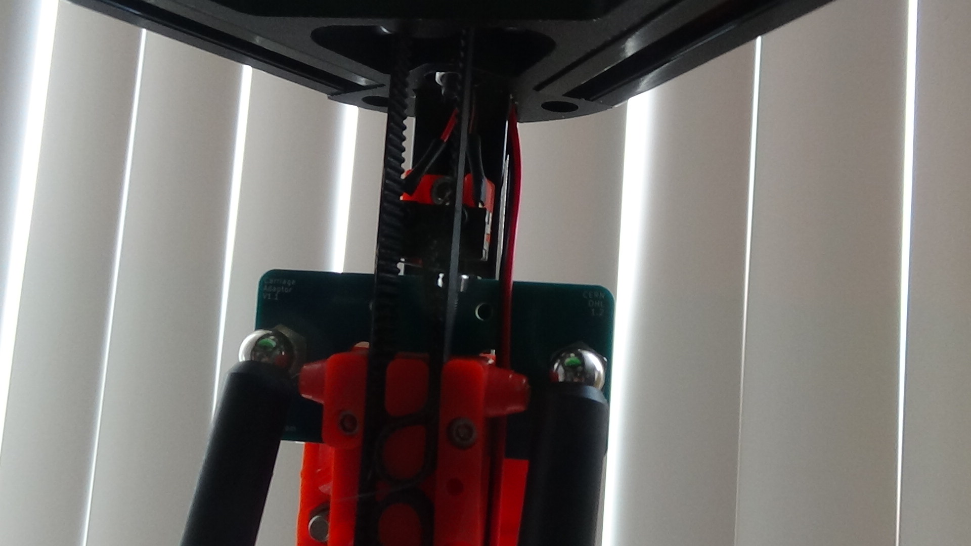
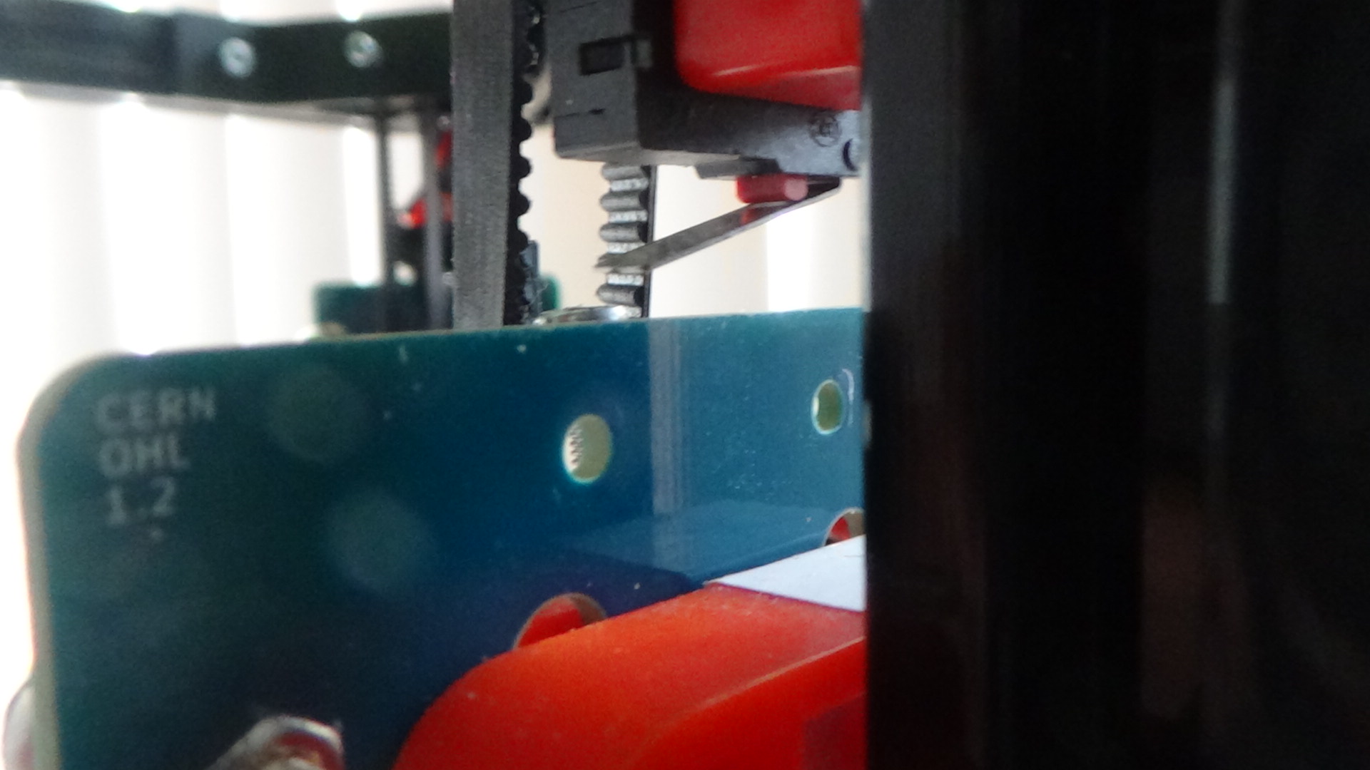
This photo is the Z pillar after homing.

This is from pillar X

This is from pillar Y

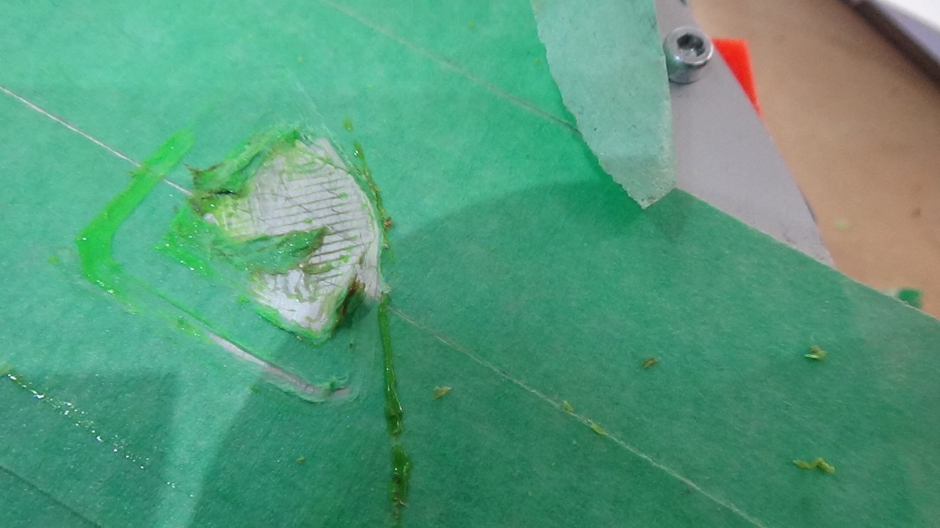
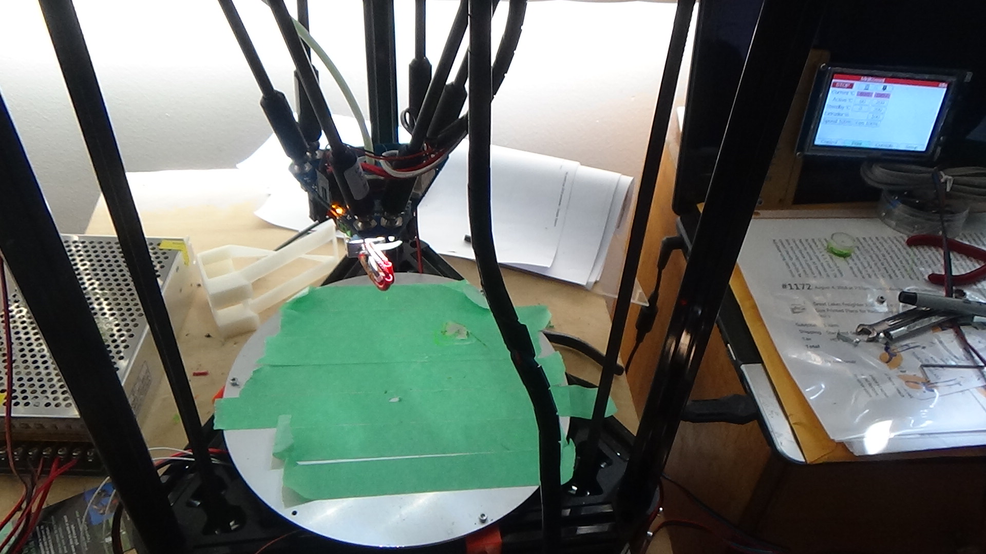
This is the most recent print of the configuration cube

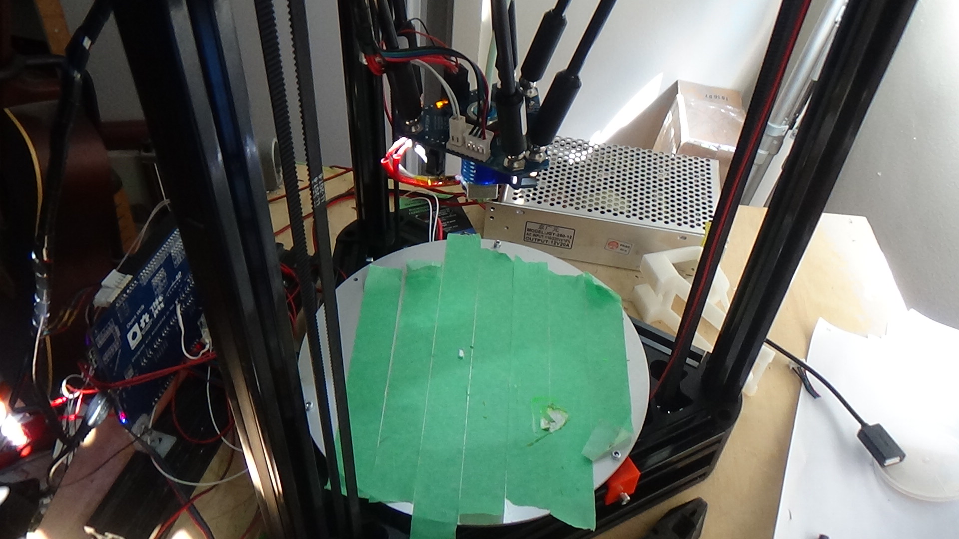
Location of Effector before print


When I printed, the nozzle caught the edge of the masking tape, so it didn't actually dig into the bed.
You can see the rim and the start of the cube in DSC816. In the back of the cube, you can see where it tried to lay down filament on the bare bed, and you can see how the nozzle tracks in an arc across the back corner. The rim obviously did not fit within the print area.
Edited for putting the wrong photo in for Y -
-
When you run auto calibration, does the nozzle sometimes touch bare parts of the bed and sometimes parts with masking tape on them? If so, that might explain why your calibration deviation is worse than we expect when using the Smart Effector.
-
I'm not sure if you have already done this (because this thread is so long); but can you run G29 and post the resulting height map here? That might give a clue about what is going on.
-
Have you fitted the spirit level to the Smart Effector; and if so, does it show that the effector is level at all XY positions?
-
-
Measure the distance between the top of the red block ( that one of your endstops is mounted to) and the frame of the printer. Now measure the other two ends tops in precisely the same way. They should be identical. If not you need to fix it.
It's actually easiest to do this with a 'truth stick' approach. You place an object to act as a temporary spacer between the endstop and the top frame, roughly equal to the spacing you have now. One at a time, slacken the endstop mounts and push them against the spacer, and re tighten the mount. It should only take a couple of minutes to complete and will get you to within 0.5mm without difficulty.
If your endstops are already a very close match then we need to know, as something else must be amiss which could be confusing the situation.