effector tilting into bed on print
-
@timvukman said in effector tilting into bed on print:
No Faults came up.
OK, so have you saved that result into the config-override.g by running M500? Alternatively, you can (and probably should) put the results into the M307 in config.g, the tuning is unlikely to change unless you make hardware changes.
I have seen situations where the model does not print at or about the center of the bed. I am assuming that it should. The favourite starting position seems to be a little on the high side of what would be X on a cartesian and a little back from center in the Y axis.
Can you post a screenshot of the "Machine" tab from the "Tools->Options" menu? Assuming you've set the machine up as a delta in there it should be set forever. If you have the Simplify3D configuration correct then the object will print on the bed in the same location and orientation as the model on screen.
Having said that, your endstop offsets are:
M666 X0.425 Y3.690 Z-4.114 A0.00 B0.00If I were you I'd try and reduce that difference. Someone else can chime in here if I'm wrong but I think the effect of those large compensations will be to move the centre of the coordinate system away from the centre of the bed. Auto calibration can be a good thing, especially on deltas, but you should make every effort to get the system mechanically correct first. In this case, when the carriages trigger the endstops, they should be at the same height above the bed from each other. Depending on the kind of endstop and/or carriage you have fitted, the method of adjustment will be different. Post a photo if you are not sure. You should be able to get to better than 1mm deviation between endstops without too much effort.
I am assuming that the hot end will step upward on each layer by the 80mm/step. What should my layer height be in Simplify3d, or will that be automatic based on the printer hardwawre?
The layer height you choose varies based on lots of parameters but it's basically a tradeoff between speed and z-resolution. For now, and assuming you are using a 0.5 or 0.6mm nozzle, I'd use something like 0.2 or 0.3mm layer height.
-
This is the result from the PID tuning of the heaters
; Heater model parameters
M307 H0 A129.5 C334.4 D0.5 S1.00 V12.1 B0
M307 H1 A490.4 C147.5 D5.4 S1.00 V12.3 B0The heater section from my config.g file is
; Heaters
M307 H0 B0 S1.00 ; Disable bang-bang mode for the bed heater and set PWM limit
M305 P0 T100000 B3950 C0 R4700 ; Set thermistor + ADC parameters for heater 0
M143 H0 S120 ; Set temperature limit for heater 0 to 120C
M305 P1 T100000 B4388 C0 R4700 ; Set thermistor + ADC parameters for heater 1
M143 H1 S280 ; Set temperature limit for heater 1 to 280CThanks for pointing out the M666 variances. I did not recheck the switches after I replaced the upper and lower frames. To that end, there was interference on the Z switch from the belt. I will shorten up the overhang.
-
New heater section
; Heaters
M307 H0 A129.5 C334.4 D0.5 B0 S1.00 V12.1 ; Disable bang-bang mode for the bed heater and set PWM limit
M305 P0 T100000 B3950 C0 R4700 ; Set thermistor + ADC parameters for heater 0
M143 H0 S120 ; Set temperature limit for heater 0 to 120C
M307 H1 A490.4 C147.5 D5.4 B0 S1.0 V12.3
M305 P1 T100000 B4388 C0 R4700 ; Set thermistor + ADC parameters for heater 1
M143 H1 S280 ; Set temperature limit for heater 1 to 280CI tightened up the belts because the looseness was bothering me.
I have rerun the Auto Configuration and it looks good to me10:25:22 AMG32
Calibrated 6 factors using 10 points, deviation before 0.089 after 0.084
10:24:08 AMG32
Calibrated 6 factors using 10 points, deviation before 0.083 after 0.080I did not get the corrections I was looking for with regard to the M666,
but I did fix the settings in Simplify3d. -
@timvukman said in effector tilting into bed on print:
I did not get the corrections I was looking for with regard to the M666,
Can you take three photos, one for each axis, that clearly shows the top of the frame and the endstop please? Ideally just after homing so we can see the carriage in relation. There must be something in the physical configuration that's giving you that large deviation. It really is worth getting that sorted.
The auto calibration looks ok - and you should be able to print - but if I were you I'd want to understand why that correction is needed.
Have you tried another cube yet?
-
What do you mean by I fixed the settings in S3D in relation to the M666?
-
Simplify3d came up defaulted to a cartesian configuration. I loaded my delta configuration and went from there
This photo is the Z pillar after homing.

This is from pillar X

This is from pillar Y

This is the most recent print of the configuration cube

Location of Effector before print


When I printed, the nozzle caught the edge of the masking tape, so it didn't actually dig into the bed.
You can see the rim and the start of the cube in DSC816. In the back of the cube, you can see where it tried to lay down filament on the bare bed, and you can see how the nozzle tracks in an arc across the back corner. The rim obviously did not fit within the print area.
Edited for putting the wrong photo in for Y -
-
When you run auto calibration, does the nozzle sometimes touch bare parts of the bed and sometimes parts with masking tape on them? If so, that might explain why your calibration deviation is worse than we expect when using the Smart Effector.
-
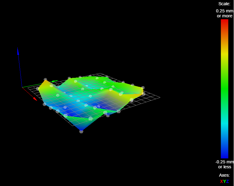
I'm not sure if you have already done this (because this thread is so long); but can you run G29 and post the resulting height map here? That might give a clue about what is going on.
-
Have you fitted the spirit level to the Smart Effector; and if so, does it show that the effector is level at all XY positions?
-
-
Measure the distance between the top of the red block ( that one of your endstops is mounted to) and the frame of the printer. Now measure the other two ends tops in precisely the same way. They should be identical. If not you need to fix it.
It's actually easiest to do this with a 'truth stick' approach. You place an object to act as a temporary spacer between the endstop and the top frame, roughly equal to the spacing you have now. One at a time, slacken the endstop mounts and push them against the spacer, and re tighten the mount. It should only take a couple of minutes to complete and will get you to within 0.5mm without difficulty.
If your endstops are already a very close match then we need to know, as something else must be amiss which could be confusing the situation.
-
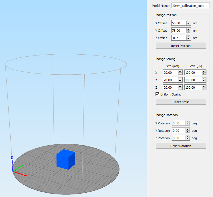
Also, for a first print, try a 20mm calibration cube. There are loads on the Web. They print quickly, come nowhere near your axis limits and are not difficult to slice.
Place it on the centre of the bed in simplify 3d.
-
When you run auto calibration, does the nozzle sometimes touch bare parts of the bed and sometimes parts with masking tape on them?
The answer is yes. I did add another piece of tape to the large blank spot at the front,
If so, that might explain why your calibration deviation is worse than we expect when using the Smart Effector.
I will run the autoconfig again after I finish this note
I'm not sure if you have already done this (because this thread is so long); but can you run G29 and post the resulting height map here? That might give a clue about what is going on.
I will do that.
Have you fitted the spirit level to the Smart effector; and if so, does it show that the effector is level at all XY positions?
With the spirit level in place, the bubble is at the back edge of the black circle, pointed directly at the Z pillar. When I place it on the table that the printer is on, it's almost perfect.
If I move the effector around, the little air bubble stays pretty much in the same place where the edge of the bubble lines up with the edge of the black circle at the rear of the machine -
4:15:50 PMG32
Calibrated 6 factors using 10 points, deviation before 0.131 after 0.126
4:15:18 PMG32
Calibrated 6 factors using 10 points, deviation before 0.142 after 0.139G29
4:18:10 PMG29
45 points probed, mean error -0.033, deviation 0.134
Height map saved to file heightmap.csv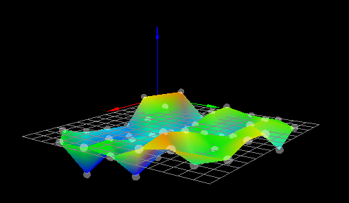
-
@adavidm
I have measured the distance on all three pillars and made sure that they are even -
@adavidm
That cube is what I was trying to print. That's what was in the photos -
4:52:21 PMG32
Calibrated 6 factors using 10 points, deviation before 0.126 after 0.121
4:51:50 PMG32
Calibrated 6 factors using 10 points, deviation before 0.137 after 0.121After measuring and adjust the home switch mounts to be physically equal
-
-
Hi Tim,
Your height map shows the classic crinkle-crisp effect along the X axis - with ridges at one end turning into valleys at the other end. This explains your unusually high calibration deviation. It is caused by backlash in the mechanics. To resolve it:
- Lubricate the magnetic joints. I used a thin smear of silicone grease on the magballs. White lithium grease should be suitable too.
- Check that the belts are taut and the idlers free to rotate.
- Check that the carriages slide up and down the towers with no significant friction, and lubricate parts as necessary. If using wheeled carriages, check that the wheels are free to rotate and not gripping the towers too tightly. With no belts or rods fitted, the carriages should drop under their own weight.
- Check that you are using sufficient motor current. 60% to 85% of the rated motor current is good.
HTH David
-
Hi dc42
Thanks for you input.I have applied some light grease. Check this out!
G32
Calibrated 6 factors using 10 points, deviation before 0.119 after 0.119
10:24:46 AMG32
Calibrated 6 factors using 10 points, deviation before 0.121 after 0.120
10:24:11 AMG32
Calibrated 6 factors using 10 points, deviation before 0.120 after 0.119Do I need to delete the previous height map, or is the .csv file overwritten?
There is no real difference in the graphed data.
I certainly do not detect any drag in the carriages. Perhaps I should invest in sliding bearings?
-
@timvukman said in effector tilting into bed on print:
Do I need to delete the previous height map, or is the .csv file overwritten?
The .csv file is only overwritten when you run G29 again, so you can delete oit to make sure you don't use it.
There is no real difference in the graphed data.
I certainly do not detect any drag in the carriages. Perhaps I should invest in sliding bearings?
I found that linear rails and bearings worked better than my previous wheeled carriages, however my wheeled carriages weren't the best. I suggest you check whether the carriages drop under their own weight if you remove the rods and belts, and if they don't then reduce the pressure of the wheels on the towers.
Duet WiFi hardware designer and firmware engineer
Please do not ask me for Duet support via PM or email, use the forum
http://www.escher3d.com, https://miscsolutions.wordpress.com -
I would appreciate some input on what is driving my print issue. It's not as obvious in yesterday's photos as it will be in the one I post later today. When printing the calibration cube, the rim is being rounded at the right rear corner, as is the cube.
The obvious deduction would be that the printing is at or near or overlapping with the outer radius of the print area defined on the print bed.That brings me to the point I made earlier that my print is not starting in the area of the center of the bed.
I will include a photo of S3D where you can see that there are offsets in the settings in the top right boxes. I have tried removing them and resetting and recentering and repositioning everything I can find that pertains to those settings, but I can't get rid of them.
Also, while the web interface indicates that the Z height is rising layer by layer, the physical print has the nozzle plowing around in the filament that has been laid down. The nozzle is not going up, or is going at way too slowly.


-
@dc42
I will look into the linear rails. I unfortunately have metal wheeled carriages on order. Maybe they will work out better. I do not have any pressure being applied on the carriage wheels. There are three wheels which I feel is not sturdy as the carriages can be rotated in place to some degree without a huge effort.
My carriages that came with the kit are injection molded as was everything else other than the vertical pillars and the horizontal frame pieces. I also want to change the nuts to the type that turn in the channel so they can actually be tightened. The kit came with square nuts which I do not feel have the required grip.