extruder works but print not starting
-
@marine85 said in extruder works but print not starting:
yes when i send
G91
G1 Z4 F200 S2z moves up 4 mm
but z not homming when i try to home only moves up and x , y 100So Z does move up by 4mm? In your earlier post you said:
x and Y axis only moves to 100,100 and Z not moving up or down and reading Z 4.0 ...
-
@phaedrux Thank you this solve the issue with Z homing now homing
-
@dc42 this issue if solved but again another issue popped up
I am using macro to sync 4 x z motors to independent endstops and this works fine
M400 ; make sure everything has stopped before we make changes
M584 X0 Y1 Z2:3:4:5 U3 V4 W5 E6
M574 Z2 U2 V2 W2 S1 ; set endstops to max
G91 ; use relative positioning
M584 Z2 U3 V4 W5 ; split z to control z,u,v and w
G1 Z1350 U1350 V1350 W1350 F4000 S1 ; course home z
G1 Z-250 U-250 V-250 W-250 F6000 S2 ; Down Z relative to current position
G90 ; back to absolute positioning
M400 ; make sure everything has stopped before we reset motors current
M584 Z2:3:4:5 ; combined z again
M574 Z2:3:4:5 S2 ; set endstops back to normal
M999my config.g file is now
; Configuration file for Duet WiFi (firmware version 1.21)
; executed by the firmware on start-up
;
; generated by RepRapFirmware Configuration Tool on Tue Aug 21 2018 21:22:04 GMT+0400 (Arabian Standard Time); General preferences
G90 ; Send absolute coordinates...
M83 ; ...but relative extruder moves; Network
M550 PYOUNES ; Set machine name
M551 Pteignprop ; Set password
M552 S1 ; Enable network
M587 S"TEIGNBRIDGE" P"peacock1" ; Configure access point. You can delete this line once connected
M586 P0 S1 ; Enable HTTP
M586 P1 S0 ; Disable FTP
M586 P2 S0 ; Disable Telnet; Drives
M569 P0 S0 ; Drive 0 goes forwards
M569 P1 S0 ; Drive 1 goes forwards
M569 P2 S0 ; Drive 2 goes forwards
M569 P3 S0 ; Drive 3 goes forwards
M569 P4 S0 ; Drive 4 goes forwards
M569 P5 S0 ; Drive 5 goes forwards
M569 P6 S1 ; Drive 6 goes forwardsM584 X0 Y1 Z2:3:4:5 U3 V4 W5 E6 ; Apply custom drive mapping
M350 X16 Y16 Z16:16:16:16 U16 V16 W16 E16 I1 ; Configure microstepping with interpolation
M92 X80 Y80 Z640:640:640:640 U640 V640 W640 E420 ; Set steps per mm
M566 X900 Y900 Z12:12:12:12 U12 V12 W12 E120 ; Set maximum instantaneous speed changes (mm/min)
M203 X6000 Y6000 Z180:180:180:180 U180 V180 W180 E1200 ; Set maximum speeds (mm/min)
M201 X500 Y20 Z250:250:250:250 U250 V250 W250 E250 ; Set accelerations (mm/s^2)
M906 X1550 Y1550 Z2550:2550:2550:2550 U2550 V2550 W2550 E1400 I30 ; Set motor currents (mA) and motor idle factor in per cent
M84 S120 ; Set idle timeout; Axis Limits
M208 X0 Y0 Z0 S1 ; Set axis minima
M208 X1200 Y1200 Z1200 S0 ; Set axis maxima; Endstops
M574 X1 Y1 S1 ; Set active high endstops (NC); Z-Probe
M307 H3 A-1 C-1 D-1
M574 Z1 S2 ; Set endstops controlled by probe
M558 P5 X0 Y0 Z1 T4000 F300 H10 ; Set Z probe type to switch and the dive height + speeds(Analog Z probe, also used for homing the Z axis)
G31 X0 Y0 Z0 P500 ; Set Z probe trigger value, offset and trigger height
M557 X15:1185 Y15:1185 S100 ; Define mesh grid; Heaters
M305 P0 T100000 B4138 C0 R4700 ; Set thermistor + ADC parameters for heater 0
M143 H0 S120 ; Set temperature limit for heater 0 to 120C
M305 P1 T100000 B4725 C7.060000e-8 R4700 ; Set thermistor + ADC parameters for heater 1
M143 H1 S280 ; Set temperature limit for heater 1 to 280C; Fans
M106 P0 S0 H-1 C"Part Cooling" ; Set fan 0 (Part cooling blower) G-code controlled. Thermostatic control is turned off
M106 P1 S1 H1 T45 C"Hotend Fan" ; Set fan 1 (Hotend fan) Thermostatic control. Turns on when hotend reaches 45c
M106 P2 F100 L0.2 B0.5 T30:40 H100:101:102 C"Duet Fans" ; Set fan 2 Duet case fan. Tied to CPU and driver temps.; Tools
M563 P0 D0 H1 ; Define tool 0
G10 P0 X0 Y0 Z0 ; Set tool 0 axis offsets
G10 P0 R0 S0 ; Set initial tool 0 active and standby temperatures to 0C; Automatic power saving
M911 S10 R11 P"M913 X0 Y0 G91 M83 G1 Z3 E-5 F1000" ; Set voltage thresholds and actions to run on power loss; Custom settings are not configured
; Miscellaneous
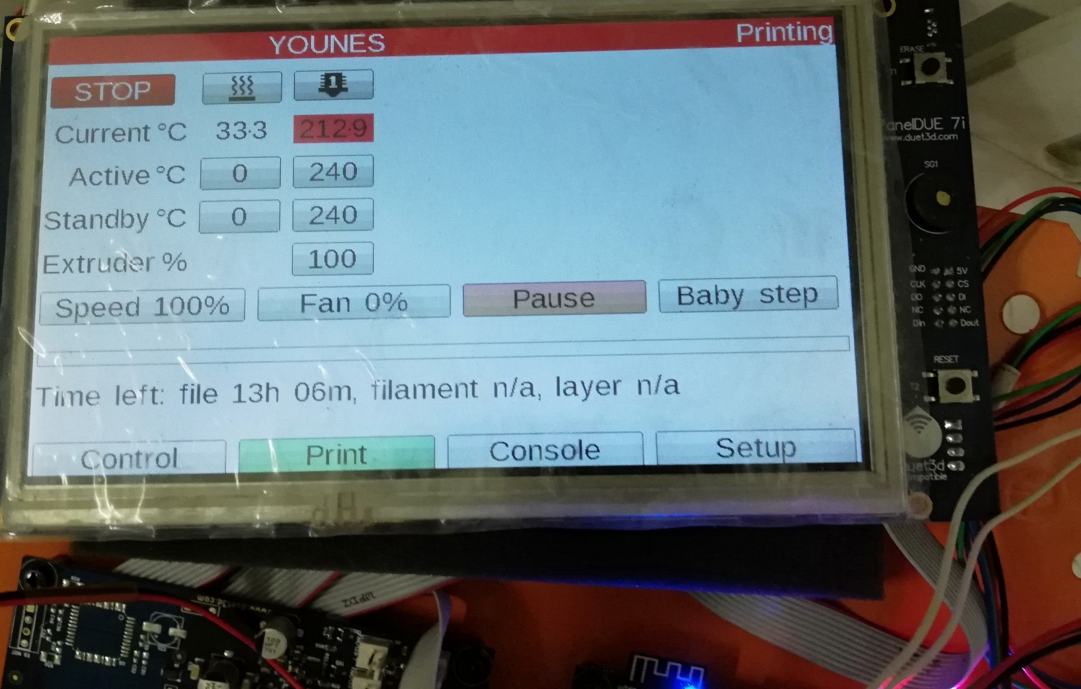
T0 ; Select first toolwhen i try to print everything looks ok

x y and z home but after that driver 3 which i dedicated to Z2 moving up and other 3 x z not moving and print not starting
i have warning message that driver 3 is hotwhat is the solution please??? I am trying to print for more than 3 weeks and no result so far

is there any special configuration i have to do in the slicer software this is the file i am trying to print this fileG90
M83
M106 S0
M104 S240 T0
M109 S240 T0
G28 ; home all axes
G1 E-1.0000 F1800
G1 Z0.600 F1002
; process Process1
; layer 1, Z = 0.600
T0
; tool H0.600 W0.720
; skirt
G1 X606.767 Y617.591 F4800
G1 E1.0000 F540
G1 X630.179 Y604.074 E4.8556 F1800
G1 X630.363 Y604.025 E0.0340
G1 X634.303 Y604.025 E0.7078
G1 X634.486 Y604.074 E0.0340
G1 X649.791 Y612.910 E3.1741
G1 X665.179 Y604.026 E3.1913
G1 X665.362 Y603.977 E0.0340
G1 X669.303 Y603.977 E0.7078
G1 X669.486 Y604.026 E0.0340
G1 X692.899 Y617.544 E4.8556
G1 X693.033 Y617.678 E0.0340
G1 X695.004 Y621.091 E0.7078
G1 X695.053 Y621.274 E0.0340
G1 X695.053 Y639.005 E3.1846
G1 X710.566 Y647.962 E3.2174
G1 X710.701 Y648.096 E0.0340
G1 X712.671 Y651.509 E0.7078
G1 X712.720 Y651.692 E0.0340
G1 X712.720 Y678.726 E4.8555
G1 X712.671 Y678.909 E0.0340
G1 X710.701 Y682.322 E0.7078
G1 X710.566 Y682.456 E0.0340
G1 X687.154 Y695.974 E4.8556
G1 X686.970 Y696.023 E0.0340
G1 X683.030 Y696.023 E0.7078
G1 X682.846 Y695.974 E0.0340
G1 X667.500 Y687.114 E3.1827
G1 X652.154 Y695.974 E3.1827
G1 X651.970 Y696.023 E0.0340
G1 X648.030 Y696.023 E0.7078
G1 X647.846 Y695.974 E0.0340
G1 X632.500 Y687.114 E3.1827
G1 X617.154 Y695.974 E3.1827
G1 X616.970 Y696.023 E0.0340
G1 X613.030 Y696.023 E0.7078
G1 X612.846 Y695.974 E0.0340
G1 X589.434 Y682.456 E4.8556
G1 X589.299 Y682.322 E0.0340 -
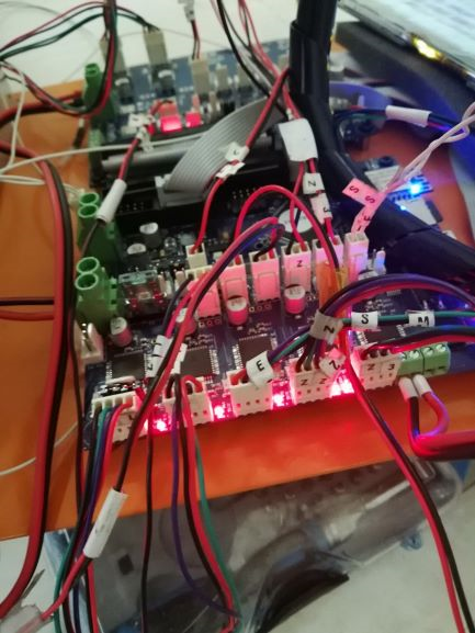
You have all 4 Z motor currents set to 2.55A, which is more than the 2.4A maximum of the Duet. So it will reduce them to 2.4A. However, with 4 drivers running at 2.4A you need to provide very good fan cooling to prevent the drivers overheating. The most important area to cool is the underside of the PCB underneath the drivers. Best is if you put a fan at the edge of the PCB to blow air along the line of drivers on both sides of the Duet. Similarly for the X5.
The optimum way of driving 4 high current motors will be one of the following:
-
Connect all 4 of them to outputs on the DueX5. This means that you will only needed to fan cool the DueX5, also the Duex5 has a larger heatsinking area of PCB per driver chip than the Duet does, so it can better get rid of the heat.
-
Connect 2 of them to outputs on the Duet, and 2 to outputs on the X5. On each of the Duet and the DueX5, choose a pair of drivers that are not adjacent, so that they don't heat each other up as much.
You could also try using a lower motor current. What type of motors are they?
-
-
Looking at the steps per mm for the Z axis, 640 seems to be an odd number to use. At 16X micro-stepping (which is what is being used) 640 micro-steps translate to 40 full steps. Assuming 1.8 degree motors which have 200 steps per revolution, then 40 full steps is 1/5th of a revolution which would imply the lead of the screw is 5mm which is a very strange number. It's possible but I've only ever seen 5mm lead screws in 22 or 28mm diameter.
If the motors are 0.9 degree (400 steps per revolution) , then 40 full steps would 1/10th of a revolution which would imply a 10mm lead on the screw which is very coarse and would likely be 30 to 40 mm in diameter.
Is there some gearing arrangement between the motors and shafts? i.e are there asymmetric pulley sizes? Can you post details of the screws and drive arrangement?
If the steps per mm are indeed correct, then driving them directly will require a lot of torque, so high power motors. A finer lead or gearing will reduce the torque requirement and allow lower motor current to be used.
-
@dc42 I am using this motors https://www.aliexpress.com/item/NEMA23-stepper-motor-57x112mm-4-lead-3A-3N-m-Nema-23-motor-112mm-428Oz-in-for/1781700551.html+i am using duex 2 I will get duex5 and reduce the current.
I had a weird behavior for z when assigning the Z to 2 ,4 and 5 the macro not working!
when assigning to 2,3,4 and 5 works well , this with duex2 i will try with duex5 -
@deckingman said in extruder works but print not starting:
the motors are 0.9 degree (400 steps per revolution) , then 40 full steps would 1/10th of a revolution which would imply a 10mm lead on the screw which is very coarse and would likely be 30 to 40 mm in dia
the motors are 1.8 degree and the pitch for the pull screw is 5mm,diameter is 16mm
the problem i the bed is abit heavy and requires these motors to lift and lower and they are working well now
the problem when trying to print now , driver 3 giving overheating warning and acting independently after x and y homed for printing -
As well as cooling the drivers better, you should use the P parameter in the M584 command to hide the additional axes when you are not using them, and un-hide them when you need to move them independently. That should make them all work together.
-
@marine85 said in extruder works but print not starting:
@deckingman said in extruder works but print not starting:
the motors are 0.9 degree (400 steps per revolution) , then 40 full steps would 1/10th of a revolution which would imply a 10mm lead on the screw which is very coarse and would likely be 30 to 40 mm in dia
the motors are 1.8 degree and the pitch for the pull screw is 5mm,diameter is 16mm
the problem i the bed is abit heavy and requires these motors to lift and lower and they are working well now
the problem when trying to print now , driver 3 giving overheating warning and acting independently after x and y homed for printingAhh, OK. As I said earlier in my post (which you haven't included in your quote) , I've never seen 5mm lead in anything other than 22mm diameter. Out of curiosity, what are the dimensions of the bed and how much does it weigh?
-
Bed is 1300x1300 and used 25mm hiwin rails which they are really heavy and aluminum profiles 60x60 i would say it is about 35g i have a plan to make it lighter less than the half but now with these motors lifting is very smooth apart from the overheating issue
I will reduce the supply amps into 1350 amps and keep the duetwifi and duex in air-conditioned room and check
Hopefully it will print -
@marine85 Yes, that's pretty big. I think if it were me, and if it's possible to fit, I'd look at using small pulleys on the motors and a large ones on the screws to give some gearing. That would reduce the torque requirement for the motors. Basically if you had 2:1 gearing, you halve the torque required. But on te other hand, you do have 4 motors so if you can drive the bed OK with lower current, then there is no need.
-
Many Thanks all for great support , I got it working

but when I use the hide parameter P3 in M584 stops the macro for independent Z endstops? -
Use M584 P5 within that macro to un-hide the U and V axes before you move them, and M584 P3 again afterwards.