Leadshine BLM57180 Servos
-
I can upload additional info tomorrow including my config...but I’m currently sitting dead in the water.
This custom machine has the Leadshine servo installed already and alternate options are not currently available.
-
@ajlapp said in Leadshine BLM57180 Servos:
BLM57180
Hi ajlapp.
Am planning to implement servo in my project too ( rotary delta robot ). Can you share some schematics how you hook up all three servos to duet ? . What power supply and servo driver do you use ? Thank you in advance for your reply ! -
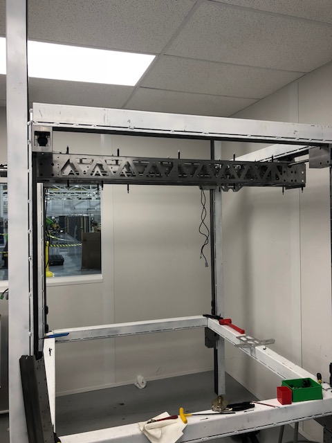
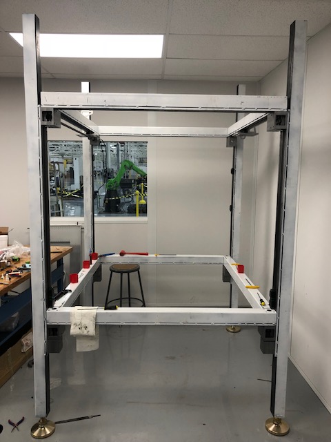
@arnix I'm attempting to use the Leadshine ACS806 with a matching BLM57180 motor. This is for a large volume printer, approximately 40" in. cubed.
These drivers accept direct step and pulse data. I have gotten the driver to repsond to the Duet, but the output is unpredictable. Yesterday I felt that I had things sort of working but after a restart the motor changed behavior. I'm sure this is a problem specific to the Leadshine.
I currently just have the X axis steeper lines connected directly to the ACS806.
My gut says that these Leadshine servos were a bad choice so for now I've ordered some backup Nema23 steppers to keep the project rolling. This is a corporate build and my deadline is looking.

-
@ajlapp said in Leadshine BLM57180 Servos:
I'm using BLM57180 servos with a Duet3D. I have them driving but I'm getting different speeds and amounts of rotation when commanding forward and reverse moves? Not sure why this would happen.
Have you extended the step pulse timing for your step-servo drives, using the T parameter of the M569 command/ This is mandatory for most external drivers.
Also, I need to have multiple motors on all axes and it's not clear how to have two actuators on each axis...this is probably specific to RepRap setup but I have no experience with this particular package. Any help is appreciated.
Look up the M584 command on the GCodes wiki page.
-
Yes, I've tried extending the timing...my commands look like this currently:
M569 P0 S0 T8.5:8.5:50.0:67.0 D0
M350 X1 I0
M92 X400.00Currently the motor moves but isn't consistent between clockwise and counter-clockwise rotation. Also it's clear to me what the actual steps/mm will be.
The BLM motor states that it has a 1000 line encoder. My ball screw is 10mm pitch...so one revolution will yield 10mm of travel. My initial guess is that the 1000 line encoder actually yields 4000 counts in quadrature. So 400 steps/mm.
This doesn't produce very favorable results...so now I've switched to this:
M569 P0 S0 T8.5:8.5:50.0:67.0 D0 ; Drive 0 goes forwards
M350 X16 I1 ; Configure microstepping with interpolation
M92 X14000.00 ;This drives pretty good, but doesn't turn a consistent amount in CW/CCW. The steps/mm are just a swag...I'm just using trial and error.
It's also very slow.
-
@ajlapp said in Leadshine BLM57180 Servos:
M569 P0 S0 T8.5:8.5:50.0:67.0 D0 ; Drive 0 goes forwards
M350 X16 I1 ; Configure microstepping with interpolation
M92 X14000.00 ;P0 is the first internal driver on the Duet.- The first driver on the breakout board is P5, not P0. So use P5 in your M569 command. I assume you are using the breakout board.
- M350 doesn't have any effect on external drivers.
-
If the servo drive has optocouplers you probably need a 5-24 volt signal that can source or sink >2ma.
-
I assume I still use M92 to set steps/mm....how does that look? Is P5 then referenced as E2?
M92 E2:5000; Something like this?
-
I have integrated a few different servo motors and here are a few odd things I have run into.
- signal timings as mentioned by David. Dir change especially can be tricky because it's not always listed on data sheets so try large-ish values. Looks like you need 0.85us min pulse width for step signals on the ACS806.
- signal voltage levels - check to make sure you are getting high enough voltage on the step/dir compared to the data sheet for the servo drive. Yours should accept anything over 4V.
- Make sure your signal GND is good. If this is not a good ground reference you will never get repeatable performance from the system.
Depending on the servo software you might also be able to get a readout of the commanded position or input signal as you test. This will let you know where you are dropping steps or where the signal is getting funky.
-
@ajlapp said in Leadshine BLM57180 Servos:
I assume I still use M92 to set steps/mm....how does that look? Is P5 then referenced as E2?
M92 E2:5000; Something like this?
No, still as X. The M584 command is the one that tells the firmware that you are using driver 5 for the X axis (which is what I assume you are doing - you haven't posted your config.g file so I can't check).
-
Config below. Ultimately I'm hoping to use two of these BLM57180 servos for the X axis. All of my testing had been completed with the servo connected to P0...the config below is me trying to switch to P5.
; Configuration file for Duet WiFi (firmware version 1.21)
; executed by the firmware on start-up
;
; generated by RepRapFirmware Configuration Tool v2 on Wed Jan 16 2019 13:17:53 GMT-0500 (Eastern Standard Time); General preferences
G90 ; Send absolute coordinates...
M83 ; ...but relative extruder moves; Network
M550 P"AAM_Large_Volume_Printer" ; Set machine name
M551 P"password: ; Set password
M552 P10.0.0.55 S1 ; Enable network and set IP address
M553 P255.255.255.0 ; Set netmask
M554 P192.168.1.254 ; Set gateway
M586 P0 S1 ; Enable HTTP
M586 P1 S0 ; Disable FTP
M586 P2 S0 ; Disable TelnetM584 X0:5 Y1 Z2 E4;
; Drives
M569 P1 S1 ; Drive 1 goes forwards
M569 P2 S1 ; Drive 2 goes forwards
M569 P3 S1 ; Drive 3 goes forwardsM569 P5 S0 T8.5:8.5:50.0:67.0 D0 ; Drive 0 goes forwards M569 P0 S0 T8.5:8.5:50.0:67.0 D0
M92 X400.00 ;M92 Y80.00 Z4000.00 E400.00 ; Set steps per mm
M566 X6000.00 Y900.00 Z12.00 E120.00 ; Set maximum instantaneous speed changes (mm/min)
M203 X30000.00 Y6000.00 Z180.00 E1200.00 ; Set maximum speeds (mm/min)
M201 X500.00 Y500.00 Z20.00 E250.00 ; Set accelerations (mm/s^2)
M906 X2000.00 Y800.00 Z800.00 E800.00 I30 ; Set motor currents (mA) and motor idle factor in per cent
M84 S30 ; Set idle timeout; Axis Limits
M208 X0 Y0 Z0 S1 ; Set axis minima
M208 X1000 Y1000 Z1000 S0 ; Set axis maxima; Endstops
M574 X1 Y1 S0 ; Set active high endstops; Z-Probe
M574 Z1 S2 ; Set endstops controlled by probe
M558 P1 H5 F120 T6000 ; Set Z probe type to unmodulated and the dive height + speeds
G31 P500 X0 Y0 Z2.5 ; Set Z probe trigger value, offset and trigger height
M557 X15:0 Y15:195 S20 ; Define mesh grid; Heaters
M305 P0 T100000 B4138 R4700 ; Set thermistor + ADC parameters for heater 0
M143 H0 S120 ; Set temperature limit for heater 0 to 120C
M305 P1 T100000 B4138 R4700 ; Set thermistor + ADC parameters for heater 1
M143 H1 S280 ; Set temperature limit for heater 1 to 280C; Fans
M106 P0 S0.3 I0 F500 H-1 ; Set fan 0 value, PWM signal inversion and frequency. Thermostatic control is turned off
M106 P1 S1 I0 F500 H1 T45 ; Set fan 1 value, PWM signal inversion and frequency. Thermostatic control is turned on; Tools
M563 P0 D0 H1 ; Define tool 0
G10 P0 X0 Y0 Z0 ; Set tool 0 axis offsets
G10 P0 R0 S0 ; Set initial tool 0 active and standby temperatures to 0C; Heaters
M305 P0 X151 T"J"; Automatic saving after power loss is not enabled
; Custom settings are not configured
-
@ajlapp You would just use
M92and the axis name. The drives would be mapped to an axis usingM584so it would end up looking something like this (this is assuming you have two separate drives hooked up to 5 and 6 which you want to drive together for the X ax):M584 X5:6 ; map drive 5:6 to X axis
M350 X1 I0 ; set microstepping mode, full step with no interpolation
M92 X400 ; set steps/mm for X axis (drive 5 & 6)
M569 P5 S0 T8.5:8.5:50.0:67.0 ; set drive timings for drive 5 (first drive on breakout board)
M569 P6 S0 T8.5:8.5:50.0:67.0 ; set drive timings for drive 6 (second drive on breakout board)How was the servo drive originally connected to the 0 output? And how are the new motors wired up? Do you have them daisy chained via an encoder cable or something or are they both just hooked up to the drive output?
-
Solved
For one axis anyways...
I've always had the ACS806 wired directly into the stepper motor 4-pin connection....this was doing something so it seemed correct to me.
Anyway, I saw in the docs that the "expansion board" had dedicated pins for Step and Direction....so I wired directly to these pins on the 50-pin expansion port and it works perfectly.
So now my question is...can I wire to the 4-pin ports and can I ultimately use P0, P1 and P2? I have seven actuators and an extruder on this machine.
Thanks for all the help so far!
-
I suggest you use one of the internal stepper drivers for the extruder. The maximum number of independently-controlled external stepper drivers supported without changing the firmware is 7, made up of 5 on the expansion connector and 2 on CONN_LCD.
-
If two of the actuators are always running together (twin x) you might try using just one step/dir output for both drivers. Assuming your setup is like this
2 X actuators
1 Y actuator
4 Z actuators (all independent)If this is correct you could do something like the following
Drive 5: both X motors
Drive 6: Y motor
Drive 7, 8, 9, 10: Z motors
Drive 11: Extruder motor -
I think both of those are workable solutions.
I should be operational sometime next week.
I’ll load some pics once the magic starts.
Thanks again.