[not yet solved] Tevo Little Monster DuetWifi errors
-
Ah

Ok so im not dumb
Now I mount the RC3. I'll be the first on the other side the Atlantic Ocean that will try the RC4
So my brain can stop fry for some hour
-
Damn found it... but just now that you told me. Any way thanks for the patience and the support...
@kuhnikuehnast said in Firmware 2.02 Release candidate 3 now available:
Interesting thing I found about G30:
- If you use:
G30 X20 Y20to probe the bed at a specific point, you always have to calculate the offset of the probe, because the coordinates of the nozzle are used.
Whereas if you use 2:
G30 P0 X20 Y20 H0 Z-99999the offset of the probe is already calculated and the real probe coordinates are used but not the "actually" coordinates of the nozzle
- The H- parameter is still not taken into account when probing. Therefore, I performed a little test:
M561                                                    ; delete any bed transformation
G1 X45.457 Y8.602 Z10 F15000				; go to probing point on floating bed
G30 X45.457 Y8.602 H0 S-1   				; define this point as Z=0

M561                                                    ; delete any bed transformation
G1 X45.457 Y8.602 Z10 F15000				; go to probing point on floating bed
G30 X45.457 Y8.602 H5 S-1   				; define this point as Z=0

M561                                                    ; delete any bed transformation
G30 P0 X20 Y20 H0 Z-99999 S-1			        ; probe point P0

M561                                                    ; delete any bed transformation
G30 P0 X20 Y20 H3 Z-99999 S-1			        ; probe point P0

M561                                                    ; delete any bed transformation
G30 P1 X20 Y20 H3 Z-99999 S-1			        ; probe point P1
This ended up in the results:
20:20:45G32 bed probe heights:, mean nan, deviation from mean nan
20:20:42G32 bed probe heights: 0.004, mean 0.004, deviation from mean 0.000
20:20:39G32 bed probe heights: 0.007, mean 0.007, deviation from mean nan
20:20:36Stopped at height 1.399 mm
20:20:31M98 P"0:/macros/Test H-Factor"
Stopped at height 1.399 mm
So as the H-factor differs every probe, the results are all the same...

greetings kuhni
-
Im still trying...lets see what we reach.
In the same time I bought the original Genuine E3D V6 Hot-End
https://www.amazon.it/gp/product/B07CN8JP47/ref=od_aui_detailpages00?ie=UTF8&psc=1
I was looking the the Pico 3D but on the site is sold out and they never answered to my mail.
I'll let you know how the work proceed. -
So...
Some considerations...1)There is not any difference if I select S6 or S7-S8-S9 in the bed.g, the print result is pretty the same , also if the parameter auto calculated differ a lot.
- I produced right now several bed.g file and all of them have "H" parameter reconfigured. (12 external point and 3 inside or 6 outside and 6 inside)
BUT there is something strange in the procedure.
The trigger height for each point have a reasonable difference between each other. I calculated the difference and added into the bed.g BUT still the point stay too high or too low.
So the trigger eight is not the only parameter that affect the distance from the bed.
I choose to lock the S parameter in the bed.g at 6 because the automatic calculation fix the rod length at 411+ instead than 397+ as I measured with the ruler. (in the original firmware there is settled 397.1073 that confirm the distance).
>>> Concrete example: I'm gone for this point during a test with (6 out points + 6 inner points)
-Removed any old Z offset.
-G1 X112.41 Y64.90 (nozzle down at G1 Z3 from home position, moved to the XY coordinate and with incremental steps dug to the bed)
Then M280 P3 S160 I1 - G92 Z0 - G1 Z5 - M280 P3 S10 I1 - G30 S-1.
The trigger height is 1.320 . Measured several time . Is consistent, all the attempts are more or less the same.
In the center (x0 y0) the trigger height is 1.100
So 1.320-1.100=0.220 The H parameter is H0.220.
BUT if after the calibration (G32x3) I reach that point I can see that there is still 0.250mm from the bed!!! (used a thickness gauge - and if nozzle down 5 times of 0.05 i can touch the bed so is a real 0.25)
The other points do almost the same despite they are too low or high.
So...WHY?
I'm missing something?
(the endstop are all leveled with digital caliper - The motors are all the same and well wired. I can print a more or less amazing test cube.Thanks for any suggestion
")
I understood that the delta printer have those tolerances ..BUT !
If is this the case the trigger procedure as explained dont solve the problem.
There is not solution that go by attempts all the times for each point? - I produced right now several bed.g file and all of them have "H" parameter reconfigured. (12 external point and 3 inside or 6 outside and 6 inside)
-
There was a bug in the firmware whereby H parameters on G30 commands were ignored if deployprobe.g and retractprobe.g files were used, for example for BLTouch. This has been fixed in firmware 2.02RC5.
-
I ordered the extension volcano for the original D3D hotend. Both should arrive in this week .
I'll restart the calibration process after I assembled the new components. Don't want do the work twice. I bought also some copper nozzle. Ole! -
Dear absoluT...
I got it....
I made some further change at the setup I'll explain in an other post but some summing here:
-D3D original hotend + volcano extension as the original TLM. + copper nozzle (nickel coated)
-Changed belts with ones iron cored.
-Cartridge modified for a far better precision (with Teflon thickness + bi-adessive scotch) .
-Borosilicate custom made glass (x2) 41,5cmX5mm + 3 auto-build support for block the glass.
-The damn white glue really work! Moisture of 2/5 glue-water , I used just a sponge for apply it. Than the bed at 50 degree. The big piece doesn't move from the glass!Thanks to any one for the support...for sure I'll ask other stuffs...but right now I'll give back my contribution opening a new thread with my accomplishments.
I'll mark as solved the 3d. -
Hello,
I also have a Tevo Little Monster and I would like some help to understand what I badly parameterized to have this form of card in comparison to that of giostark.
I enclose you bed.g and config.g!
Thanks

bed.g
0_1549405330644_bed.gconfig.g
0_1549405365128_config.g -
That height map looks very good to me. Is there a problem?
-
Yes, it's the same printer as Giostark so why the map is not more circular as can be seen on the Giostark map above.
I am french and use googletrad and the tracduction of technical words to link to the impression are poorly translated. I still do not understand why my 1st layer is still so bad.
I can tinker with some modify G31 P25 X0 Y20 Z0.84 but it's perfect. I think that on the mechanical side the printer is well tuned but I must not understand something in the calibration procedure.I do not know what information to bring for help with my problems.


-
My guess is that you have a Z probe that is offset from the nozzle and you have a geometrical error that causes the effector tilt to vary with XY position. This causes the apparent trigger height of the Z probe to vary with XY position. It's possible to correct for this using H parameters on the G30 commands in bed.g, but tedious.
-
I will try to control all these points but it is not obvious to be precise. By the way, what is the order of magnitude XX.XXXmm?
When I do my calibrated to find the value G31 ZX and that I launch my impression I always 0.20mm too high. So I change the value of G31 Z0.687 + 0.20 to have a 1st layer that hangs and rotates between 0.25 and 0.35mm.
I controlled the distances between the top of the printer and a point of the carts that had different values. I now have about 4cm everywhere I will try to do this with the caliper.

But it did not really change the quality of my first layer (Nozzle 0.8mm)

L'imprimante

-
dc42
what should be changed as parts to solve this problem of geometry? -
Try this guide and join this TLM group, https://www.facebook.com/groups/TEVO.Monster.Delta.Owners/
-
I thank you, I will study with precision.
-

Hello,
I just control the angle of the towers and I do not have the same exactly the same value. This can be my geometry problem?
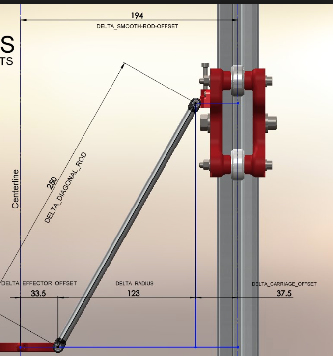
I will now control the length of my Delta Diagonal Rod -
Auto calibration will sort out the tower angles for you.
-
I think it would be complementary to bring illustrations and or videos to the Duet manual on the essential control points of a perfect machine calibration. Especially for the illiterate technicians like me.
-
I still do not understand the procedure of calibrating a delta with Duet but I will not give up. how to disable auto calibration? I think I can have a 1st more homogeneous without the self calibration. I checked everything manually and my tray with borosilicate glass is really flat.
-
My geometry problem may come from this problem (see video)
When I make a home and I go back 5mm to put out the leds of the endstops I always have an endstop that stays on.
I change endstop, screwed to racemess and unscrewed to lengthen the head of the screw, set the ten micro to have exactly the same distance between the three cart and the problem is the same, the led remains lit while the trolley is perfectly in front of the optical fork. When I push the cart slightly, the led goes out.Can you help me understand this problem?
https://www.icloud.com/iclouddrive/0od7VaaViYMMcV5_HiBiwm8dA#IMG_5224

