Flying extruder with 4th axis
-
Hi there
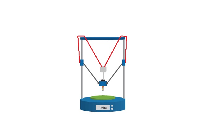
Yesterday a realized that the height it wasn´t the problem, the thing is that when going to certain corner the compensation should be different due to mechanical construction.
If you pay atention to the picture you will realize that reaching point 1 or point 2 is different because the pivoting point is not exactly where the center is, the reason for that was to keep everything well balanced.
So when reaching point 1 the teflon tube was pulling the effector and was trigerring the endstop of z probe while doing bed mesh levelling,
Is it any chance of compensating that via firmware? otherwise i would have to make a complete different system
-
i can tell you point 1 and point 2 parameters
-
The height of the extruder needs to be lower when the effector is at point 1 than it is when the effector is at point 2. You can achieve this by specifying the XY coordinates of the 4th tower (in the M669 command) as being closer to point t than to point 2. I think that to a first approximation, the coordinates of the pivot point may be about right.
Duet WiFi hardware designer and firmware engineer
Please do not ask me for Duet support via PM or email, use the forum
http://www.escher3d.com, https://miscsolutions.wordpress.com -
@ander
What if you just place the extruder assembly fixed to the top of that arm that way you take the pivoting of the assembly out of the equation, or, would simply adding some more tubing allow for the assembly to move without restriction? -
@dc42
M666 function on the new Axis,I am actively testing the new feature changing M669 and M665 R with my delta, 300mm diameter, 410mm z_height from center to center
Here is my case.
I placed 4th_axis near the print edge. M669 X0 Y-140.
And set the rod length of this new axis as same as other towers.When I home all the tower and bring the carriages down a little, let's say 20mm. And move the effector toward the new axis, G1 X0 Y-140.
Then 4th_tower's carriage hit its end_stop( Printer doesn't actually hit the end_stop physically, rather change z_height to avoid physical touch.)
Can it be solved by adding U_axis end_stop offset something similar to M666 and ignore end_stop sensing after homing?When I move the carriages down 30mm from home position, so this is not a big issue. What makes me chore is every time I adjust the PTFE tube from effector to the extruder motor hanging. I have to move the end_stop to proper position physically with a wrench.
I think this can be solved by adding the end_stop offset to the new axis, such as M666.
-
Hi,
I don't know if can help us...
I have a TLM it's a 500 mm tall printer... In the moment of rework extrusion sistem.... I have see that if I use a bowden sistem the ptfe tube has to be very long....
The original sistem uses a fliying extruder fixed to tower carriages with belts... But don't like a lot, maybe this can interfere in towers movement...
At the end I am using a bowden sistem... But with a pulley and a counter weight... That rest moving mass... After I will send photos...
This system allows me to have the extruder about 150 mm from the Print head without practically adding it to that...
This system has the advantage than so not need mechanical (motors)
After I will add photos.
-
@jooil said in Flying extruder with 4th axis:
@dc42
M666 function on the new Axis,I am actively testing the new feature changing M669 and M665 R with my delta, 300mm diameter, 410mm z_height from center to center
Here is my case.
I placed 4th_axis near the print edge. M669 X0 Y-140.
And set the rod length of this new axis as same as other towers.When I home all the tower and bring the carriages down a little, let's say 20mm. And move the effector toward the new axis, G1 X0 Y-140.
Then 4th_tower's carriage hit its end_stop( Printer doesn't actually hit the end_stop physically, rather change z_height to avoid physical touch.)
Can it be solved by adding U_axis end_stop offset something similar to M666 and ignore end_stop sensing after homing?When I move the carriages down 30mm from home position, so this is not a big issue. What makes me chore is every time I adjust the PTFE tube from effector to the extruder motor hanging. I have to move the end_stop to proper position physically with a wrench.
I think this can be solved by adding the end_stop offset to the new axis, such as M666.
I don't understand the problem you are describing. The length you set for the 4th rod should be the length of the Bowden tube - or a little less than that, to allow the Bowden tube to take up a curve. If you change the length of the Bowden tube, you will need to adjust that "rod length" in config.g. Since you have to home all 4 towers together, it is also inevitable that if you change the Bowden tube length, you will need to change the position of the 4th endstop, so that all 4 towers can home together.
Duet WiFi hardware designer and firmware engineer
Please do not ask me for Duet support via PM or email, use the forum
http://www.escher3d.com, https://miscsolutions.wordpress.com -
@dc42
I understood.
I just want to know if you have some plan to add offset function to the new axis. -
Interesting upgrade. Since discovering deckingmans machine I have been thinking about that issue.
I have a 1m tall kossel style printer with smart effector and the bondtec QR (the one with geared motor), so I first did a classic flying extruder with rubber bands connected to the carriages, but there was too much bouncing around.
So I started using counterweights (pic on thingiverse). On top of each tower I have now one of these https://www.thingiverse.com/thing:3467741/ that use two grove bearings to connect a little bucket filled with plaster of paris that rides up and down the towers. That balances the extruder quite nicely.
I wonder would you would say is the advantage of motorized version of this is?
Cheers
-
@jooil said in Flying extruder with 4th axis:
@dc42
I understood.
I just want to know if you have some plan to add offset function to the new axis.I hadn't planned to , but it could be done. If you used it then when you home the printer, the distance between the extruder and the effector would be incorrect (by the amount of correction you used) when you home the printer; but it would be corrected when you perform the first move (e.g. the 5mm downward motion that is typically at the end of the homedelta.g file). Is that really what you want?
Duet WiFi hardware designer and firmware engineer
Please do not ask me for Duet support via PM or email, use the forum
http://www.escher3d.com, https://miscsolutions.wordpress.com -
@sungod3k I used to use the "pulley and counter-weight" system on my CoreXY, with the extruders suspended above the hot end, from a pulley that was fixed high up, roughly in the centre of the bed. It was "kind of OK" in that it allowed me to use shorter Bowden tubes but when you think about it, every XY move has to move the mass of the counter-weight vertically. Then I changed to a separate XY gantry to hold the extruders but this was passively "dragged around" by the hot end gantry. This was an improvement but that's a lot of mass to be moving around because then you have the mass of the rails and carriages as well as the extruders themselves, and accelerations were limited. When I upgraded to 5 extruders, I added even more mass but more importantly, I was effectively using a small mass to drag around a larger mass with some degree of de-coupling between the two. The engineer in me just couldn't accept that (the inertia of a large mass will have a severe impact on the small mass coupled to it when a change of direction occurs). Also, because of the de-coupling between the upper and lower gantries there was a fair amount of flexing of the wire to wire connectors for the temperature sensor and heater which lead to a few failures.
So having the extruder gantry motorised, effectively means that I have my 3kg total mass divided between 2 gantries, each which their own 2 motors. Which means I can run twice the acceleration. Also, with them being perfectly synchronised, there is no flexing of the cables that run between the two so I have no more joint failures. Having said, the small amount of decoupling that I had when the extruders were passively driven did mean that for small moves such as zig-zag infill, only the hot end moved and the extruders effectively remained stationary.
So for me on my CoreXY (actually CoreXYUV now) having an actively driven extruder gantry is a better solution than a passive one. I would imagine that would be the case for Deltas too but I know next to nothing about them. If the existing motors will accelerate the print head as fast as you want, while still passively dragging extruders around, and there is no danger of the mechanism causing the effector to tilt, then there is probably no point in motorising the extruder gantry/tower. If on the other hand, the coupling to the extruder carriage could cause the effector tilt, or acceleration is being limited by the motor/mass combination, then using a motor to power the extruder gantry/tower will be beneficial.
-
@dc42 I Not really want the offset function anymore.
I added the following G-code to homedelta.g as your advice.
G1 Z-5 F6000 ; 5mm downward motion.
G1 U-15 F1800 S2 ; fine tune U_axis' carriage position. move down 15mmNow I can finetune U_axis' carriage position.
Thank you very much. -
@jooil said in Flying extruder with 4th axis:
@dc42 I Not really want the offset function anymore.
I added the following G-code to homedelta.g as your advice.
G1 Z-5 F6000 ; 5mm downward motion.
G1 U-15 F1800 S2 ; fine tune U_axis' carriage position. move down 15mmNow I can finetune U_axis' carriage position.
Thank you very much.I think you may find that the U carriage reverts to its standard position when you next enter a regular move.
Duet WiFi hardware designer and firmware engineer
Please do not ask me for Duet support via PM or email, use the forum
http://www.escher3d.com, https://miscsolutions.wordpress.com -
@dc42 Other towers do act as you mentioned.
But U_axis doesn't seem to revert to the standard position.
It acts like -15mm offset. If I adopt a magnetic end_stop to avoid a collision, I could even set a positive offset I suppose. -
I'll extend M666 to allow UVW endstop offsets in the next beta release.
Could you make a video of your machine printing, that I can share with others?
Duet WiFi hardware designer and firmware engineer
Please do not ask me for Duet support via PM or email, use the forum
http://www.escher3d.com, https://miscsolutions.wordpress.com -
@dc42
I will in the future.
Currently, I am not prepared for the heat bed. So actual printing is not ready to show. And the 4th tower is a bit ugly.
I can take a video of bed leveling(G32,G29) though.
Is there some dryrun G_code in Reprap firmware? I can't find it. -
I do dry runs simply by not putting any filament in the extruder.
Duet WiFi hardware designer and firmware engineer
Please do not ask me for Duet support via PM or email, use the forum
http://www.escher3d.com, https://miscsolutions.wordpress.com -
@deckingman said in Flying extruder with 4th axis:
So for me on my CoreXY (actually CoreXYUV now) having an actively driven extruder gantry is a better solution than a passive one. I would imagine that would be the case for Deltas too but I know next to nothing about them. If the existing motors will accelerate the print head as fast as you want, while still passively dragging extruders around, and there is no danger of the mechanism causing the effector to tilt, then there is probably no point in motorising the extruder gantry/tower. If on the other hand, the coupling to the extruder carriage could cause the effector tilt, or acceleration is being limited by the motor/mass combination, then using a motor to power the extruder gantry/tower will be beneficial.
Right, I hadn't considered the XY movement. Having the motor quietly resting above the effector makes sense.
I had considered building a scaffold on top of the delta, so the extruder gets strung up by only one tether, but that would maybe lead to more wobbling since 3 tethers with their friction can calm down XY motion better than just one.
As it is, I dont see an issue. Since my frame is weak im accelerating not that hard, but it could become in issue adding more inertia to moves at higher speeds.As a third option i also had thought about fixing the extruder to the carriages, but that would have meant not decoupling the extruder weight from the carriages.
Would be interesting to see if one can add a rod on top of the printer parallel to the towers that is still counter balanced but doesnt allow the extruder to move in XY.
In any case: a good opportunity for @ander to put together a upgrade kit
")
-
@dc42 I made some video of 4th axis flying extruder.
Because I am not used to video editing, I uploaded 4 separate videos on youtube. sorry about that. Pls, visit followings.- 4th axis flying extruder overview... https://youtu.be/Ig0k9NiVD94
- Side view ... https://youtu.be/hCjmkRbwGWc
- Top view ... https://youtu.be/Z_L8L-FmCf0
- Carriage view ... https://youtu.be/bgNJpSbPvUQ
If you need other scenes, just ask.
-
Your last 2 links are the same. But the second link shows the 4th axis very well. May I post it on other sites?
Duet WiFi hardware designer and firmware engineer
Please do not ask me for Duet support via PM or email, use the forum
http://www.escher3d.com, https://miscsolutions.wordpress.com