Do i need Manual bed leveling ?2 z motors not working
-
Hi
I have cartesian printer ( anet am8 )
My board is The duet wifi.
Actually i use 2 independent z motors connect to z1 and E1.
As a Probe i use The piezo orion
Do i need manual bed leveling to make the bed flat? If yes how to do that ?Thanks
-
Ideally, you want the bed to be both flat and "level". Level means in tram with the printer's axes defined by the guide rail positions. The bed should be parallel to the plane defined by the X and Y axis guide rails, and should be perpendicular to the Z axis guide rails.
Your printer lifts the X axis with two screws driven by two motors. The motors will get out of sync when the power is cycled which will tilt the X axis relative to the Z axis. You need to have some way to resync the two. You can copy the Prusa I3 technique- after turning on power and before starting a print, send the X axis to the top of the Z axis until it bangs into the physical stops, then bring it back down to the bed surface. That will get the X axis perpendicular to the Z axis. Now you also want the bed plate to be perpendicular to Z. If you have a probe on the extruder carriage, you can use mesh compensation to probe the bed at multiple locations so the printer's firmware can tweak the Z axis as as print progresses. That can correct unflatness and tilt.
If you don't have a probe, you will need a flat bed plate and some way to physically adjust its position so the surface is parallel to the printer's XY plane. That is usually done using leveling screws. 3 screws is best, but 4 or more can be made to work with sufficient messing around. Duet's manual bed leveling assist can make adjusting the bed position pretty quick and easy.
-
Ok thanks a lot
I use piezo orion for z-probe
-
Have you seen this? https://duet3d.dozuki.com/Wiki/Bed_levelling_using_multiple_independent_Z_motors
-
@phaedrux yes i have Setup with 2 z motors I will reply my config later.
Because its not working.What i want to use is 2 indepentend z motors
And mesh compensationI hope this is possible ?
Thanks a lot
-
@lui2004 said in Do i need Manual bed leveling ?2 z motors not working:
@phaedrux yes i have Setup with 2 z motors I will reply my config later.
Because its not working.With 2 independent Z motors, you can only level the bed in one direction (normally in the X direction) using the motors. So you need manual screws to adjust the bed tilt in at least the Y direction.
What i want to use is 2 indepentend z motors
And mesh compensationI hope this is possible ?
Yes.
Duet WiFi hardware designer and firmware engineer
Please do not ask me for Duet support via PM or email, use the forum
http://www.escher3d.com, https://miscsolutions.wordpress.com -
is there a how to manual screws to adjust bed tilt ?
bed.g
; bed.g
; called to perform automatic bed compensation via G32
;
; generated by RepRapFirmware Configuration Tool v2 on Thu Apr 11 2019 17:51:12 GMT+0200 (Mitteleuropäische Sommerzeit)
;M561 ; clear any bed transform
;G29 ; probe the bed and enable compensationM561 ; clear any bed transform
G28 ; home
M401 ; deploy Z probe (omit if using bltouch)
G30 P0 X20 Y100 Z-99999 ; probe near a leadscrew, half way along Y axis
G30 P1 X180 Y100 Z-99999 S2 ; probe near a leadscrew and calibrate 2 motors
M402 ; retract probe (omit if using bltouch)config.g
; Configuration file for Duet WiFi (firmware version 1.21)
; executed by the firmware on start-up
;
; generated by RepRapFirmware Configuration Tool v2 on Thu Apr 11 2019 17:51:12 GMT+0200 (Mitteleuropäische Sommerzeit); General preferences
G90 ; Send absolute coordinates...
M83 ; ...but relative extruder moves; Network
M550 P"AM8" ; Set machine name
M552 S1 ; Enable network
M587 S"**" P"" ; Configure access point. You can delete this line once connected
M586 P0 S1 ; Enable HTTP
M586 P1 S0 ; Disable FTP
M586 P2 S0 ; Disable Telnet; Driver
M584 Z2:4 E3 ; two Z motors connected to driver outputs Z and E1
M569 P0 S1 ; Drive 0 goes forwards
M569 P1 S1 ; Drive 1 goes forwards
M569 P2 S0 ; Drive 2 goes backwards
M569 P3 S1 ; Drive 3 goes forwards
M569 P4 S0 ; Drive 4 2nd Z-motor - Normally used as Extruder 1
M350 X16 Y16 Z16 E16 I1 ; Configure microstepping with interpolation
M92 X100.00 Y100.00 Z400.00 E100.00 ; Set steps per mm
M566 X600.00 Y600.00 Z18.00 E300.00 ; Set maximum instantaneous speed changes (mm/min)
M203 X6000.00 Y6000.00 Z180.00 E6000.00 ; Set maximum speeds (mm/min)
M201 X1500.00 Y1500.00 Z100.00 E10000.00 ; Set accelerations (mm/s^2)
M906 X500.00 Y500.00 Z500.00 E800.00 I30 ; Set motor currents (mA) and motor idle factor in per cent
M84 S30 ; Set idle timeout; Axis Limits
M671 X-20:220 Y0:0 S0.5 ; leadscrews at left and right of X axis
M208 X-5:205 Y0:200 ; X carriage moves from -5 to 205, Y bed goes from 0 to 200
;M208 X-33 Y-10 Z0 S1 ; Set axis minima
M208 X220 Y220 Z240 S0 ; Set axis maxima; Endstops
M574 X1 Y1 S0 ; Set active low and disabled endstops; Z-Probe
M574 Z1 S2 ; Set endstops controlled by probe
M558 P8 I1 R0.4 F300 X0 Y0 Z0 ; Set Z probe type to effector and the dive height + speeds
G31 X0 Y0 Z-0.1 P600
M557 X20:200 Y20:200 S40 ; Define mesh grid; Heaters
M307 H0 B0 S1.00 ; Disable bang-bang mode for the bed heater and set PWM limit
M305 P0 T100000 B4725 C7.060000e-8 R4700 ; Set thermistor + ADC parameters for heater 0
M143 H0 S130 ; Set temperature limit for heater 0 to 130C
M305 P1 T100000 B4725 C7.060000e-8 R4700 ; Set thermistor + ADC parameters for heater 1
M143 H1 S275 ; Set temperature limit for heater 1 to 275C; Fans
M106 P0 S0 I0 F500 H-1 ; Set fan 0 value, PWM signal inversion and frequency. Thermostatic control is turned off
M106 P1 S1 I0 F500 H1 T45 ; Set fan 1 value, PWM signal inversion and frequency. Thermostatic control is turned on; Tools
M563 P0 D0 H1 ; Define tool 0
G10 P0 X0 Y0 Z0 ; Set tool 0 axis offsets
G10 P0 R0 S0 ; Set initial tool 0 active and standby temperatures to 0C; Automatic saving after power loss is not enabled
; Custom settings are not configured
; Miscellaneous
T0 ; Select first tool -
See https://duet3d.dozuki.com/Wiki/Using_the_manual_bed_levelling_assistant. It's the same process as auto levelling with multiple motors. What happens is that when the firmware sees that the number of bed support coordinates you give in M671 is not the same as the number of Z motors in M584, it tells you the manual corrections instead of adjusting the motors.
You don't have to use bed.g for both functions; you can put one of them in a separate macro file and then run it directly. The only thing magic about bed.g is that G32 runs it.
-
@dc42 it's the reason why I have choose the manual bed level assistant with dual Z motors.
The auto bed levelling can be done with 3 Z steppers or more. -
i have now this as output
what did it mean
Manual corrections required: 0.00 turn up (0.00mm) 0.10 turn down (0.05mm) 1.36 turn up (-0.68mm)
-
Those are how many turns you need to adjust each adjusting screw. The order of the screws is the order you gave the coordinates in M671. The first adjustment is always zero, so in M671 you can choose that screw to be the least accessible one. "Up" means in the direction that raises the bed.
-
sorry for disturb you but i dont get it i cant level my bed
thats my bed see the picture i have 4 screws for leveling the bed
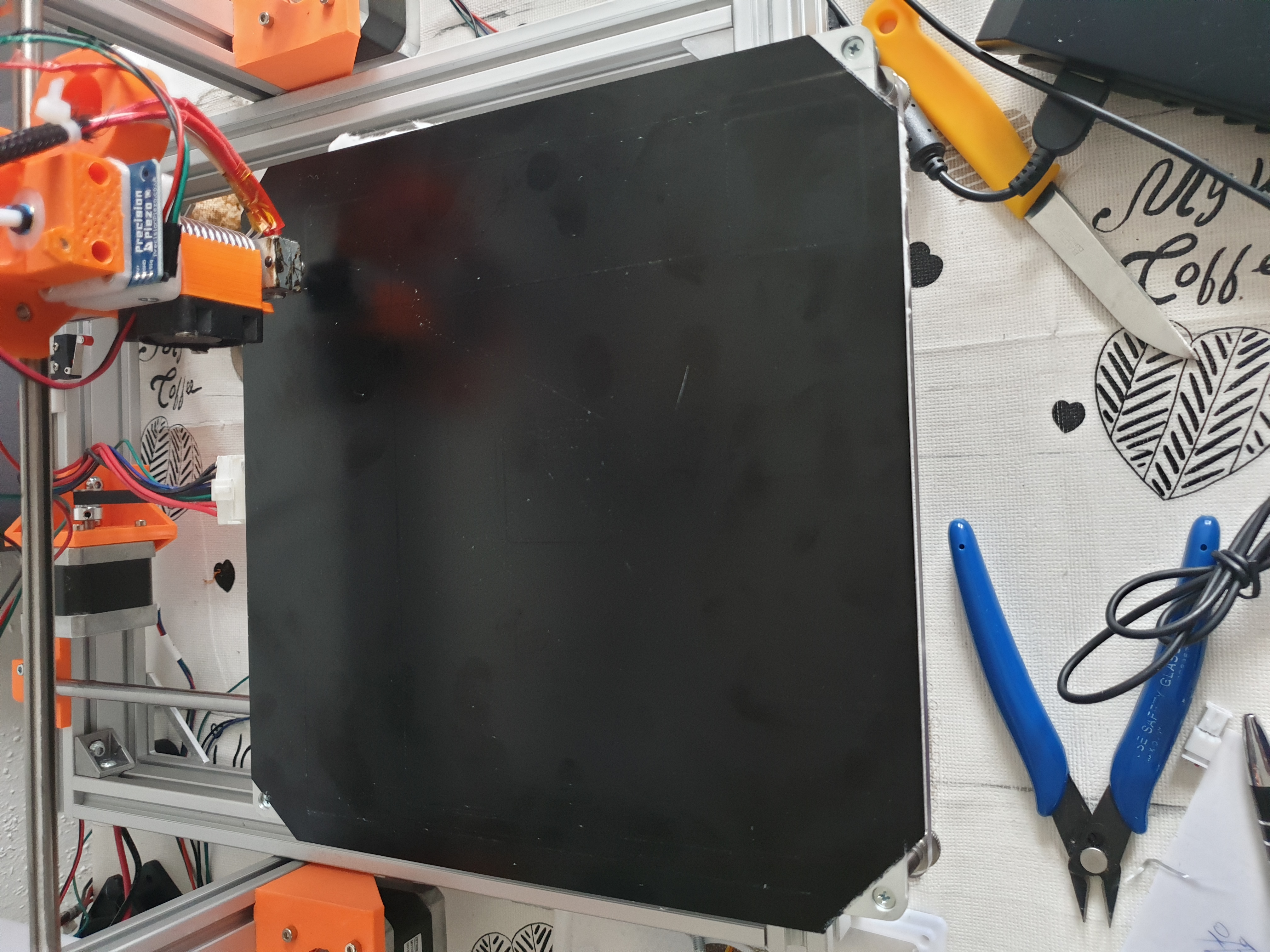
this is my actual config.g
; Configuration file for Duet WiFi (firmware version 1.21)
; executed by the firmware on start-up
;
; generated by RepRapFirmware Configuration Tool v2 on Thu Apr 11 2019 17:51:12 GMT+0200 (Mitteleuropäische Sommerzeit); General preferences
G90 ; Send absolute coordinates...
M83 ; ...but relative extruder moves; Network
M550 P"AM8" ; Set machine name
M552 S1 ; Enable network
M587 S"**" P"" ; Configure access point. You can delete this line once connected
M586 P0 S1 ; Enable HTTP
M586 P1 S0 ; Disable FTP
M586 P2 S0 ; Disable Telnet; Driver
M584 Z2:4 E3 ; two Z motors connected to driver outputs Z and E1
M569 P0 S1 ; Drive 0 goes forwards
M569 P1 S1 ; Drive 1 goes forwards
M569 P2 S0 ; Drive 2 goes backwards
M569 P3 S1 ; Drive 3 goes forwards
M569 P4 S0 ; Drive 4 2nd Z-motor - Normally used as Extruder 1
M350 X16 Y16 Z16 E16 I1 ; Configure microstepping with interpolation
M92 X100.00 Y100.00 Z400.00 E100.00 ; Set steps per mm
M566 X600.00 Y600.00 Z18.00 E300.00 ; Set maximum instantaneous speed changes (mm/min)
M203 X6000.00 Y6000.00 Z180.00 E6000.00 ; Set maximum speeds (mm/min)
M201 X1500.00 Y1500.00 Z100.00 E10000.00 ; Set accelerations (mm/s^2)
M906 X500.00 Y500.00 Z500.00 E800.00 I30 ; Set motor currents (mA) and motor idle factor in per cent
M84 S30 ; Set idle timeout; Axis Limits
M671 X-20:220 Y0:0 S0.5 ; leadscrews at left and right of X axis
M208 X-5:205 Y0:200 ; X carriage moves from -5 to 205, Y bed goes from 0 to 200
;M208 X-33 Y-10 Z0 S1 ; Set axis minima
M208 X220 Y208 Z210 S0 ; Set axis maxima; Endstops
M574 X1 Y1 S0 ; Set active low and disabled endstops; Z-Probe
M574 Z1 S2 ; Set endstops controlled by probe
M558 P8 I1 R0.4 F300 X0 Y0 Z0 ; Set Z probe type to effector and the dive height + speeds
G31 X0 Y0 Z-0.13 P600
M557 X20:200 Y20:200 S40 ; Define mesh grid; Heaters
M307 H0 B0 S1.00 ; Disable bang-bang mode for the bed heater and set PWM limit
M305 P0 T100000 B4725 C7.060000e-8 R4700 ; Set thermistor + ADC parameters for heater 0
M143 H0 S130 ; Set temperature limit for heater 0 to 130C
M305 P1 T100000 B4725 C7.060000e-8 R4700 ; Set thermistor + ADC parameters for heater 1
M143 H1 S275 ; Set temperature limit for heater 1 to 275C; Fans
M106 P0 S0 I0 F500 H-1 ; Set fan 0 value, PWM signal inversion and frequency. Thermostatic control is turned off
M106 P1 S1 I0 F500 H1 T45 ; Set fan 1 value, PWM signal inversion and frequency. Thermostatic control is turned on; Tools
M563 P0 D0 H1 ; Define tool 0
G10 P0 X0 Y0 Z0 ; Set tool 0 axis offsets
G10 P0 R0 S0 ; Set initial tool 0 active and standby temperatures to 0C; Automatic saving after power loss is not enabled
; Custom settings are not configured
; Miscellaneous
T0 ; Select first tooli am since months to get it work
-
sorry for disturb you but i dont get it i cant level my bed
I'll need more information than that:
- What macro, bed.g file or other procedure are you using to try to level it? Please provide that file or files.
- What happens when you try to level it?
-
this procedur: https://duet3d.dozuki.com/Wiki/Using_the_manual_bed_levelling_assistant
Macro i dont have it,do i need macro ?
bed.g
G28 ; home
M401 ; deploy Z probe
G30 P0 X20 Y190 Z-99999 ; probe near an adjusting screw
G30 P1 X180 Y190 Z-99999 ; probe near an adjusting screw
G30 P2 X100 Y10 Z-99999 S3 ; probe near an adjusting screw and report adjustments needed
M402 ; retract probefor 4 screws i dont know how to setup
my actual config.g
; Configuration file for Duet WiFi (firmware version 1.21)
; executed by the firmware on start-up
;
; generated by RepRapFirmware Configuration Tool v2 on Thu Apr 11 2019 17:51:12 GMT+0200 (Mitteleuropäische Sommerzeit); General preferences
G90 ; Send absolute coordinates...
M83 ; ...but relative extruder moves; Network
M550 P"AM8" ; Set machine name
M552 S1 ; Enable network
M587 S"*******" P"********" ; Configure access point. You can delete this line once connected
M586 P0 S1 ; Enable HTTP
M586 P1 S0 ; Disable FTP
M586 P2 S0 ; Disable Telnet; Drives
M569 P0 S1 ; Drive 0 goes forwards X
M569 P1 S1 ; Drive 1 goes forwards Y
M569 P2 S0 ; Drive 2 goes backwards Z
M569 P3 S1 ; Drive 3 goes forwards Extruder
M569 P4 S0 ; Drive 4 2nd Z-motor - Normally used as Extruder 1; Motor Remapping
M584 X0 Y1 Z2:4 E3 ; two Z motors connected to driver outputs Z and E1M350 X16 Y16 Z16 E16 I1 ; Configure microstepping with interpolation
M92 X100.00 Y100.00 Z400.00 E100.00 ; Set steps per mm
M566 X600.00 Y600.00 Z18.00 E300.00 ; Set maximum instantaneous speed changes (mm/min)
M203 X6000.00 Y6000.00 Z180.00 E6000.00 ; Set maximum speeds (mm/min)
M201 X1500.00 Y1500.00 Z100.00 E10000.00 ; Set accelerations (mm/s^2)
M906 X500.00 Y500.00 Z500.00 E800.00 I30 ; Set motor currents (mA) and motor idle factor in per cent
M84 S30 ; Set idle timeout; Axis Limits
M558 P5 I1 R0.4 F300 X0 Y0 Z0
M208 X-33 Y-10 Z0 S1 ; Set axis minima
M208 X215 Y200 Z195 S0 ; Set axis maxima
M671 X-33:220 Y0:0 S0.5 ; leadscrews at left and right of X axis
M208 X-5:205 Y0:200 ; X carriage moves from -5 to 205, Y bed goes from 0 to 200; Endstops
M574 X1 Y1 S0 ; Set active low and disabled endstops; Z-Probe
M574 Z1 S2 ; Set endstops controlled by probe
M558 P5 R0.4 H5 F1200 T6000 ; Set Z probe type to effector and the dive height + speeds
;G31 P500 X0 Y0 Z2.5 ; Set Z probe trigger value, offset and trigger height
G31 X0 Y0 Z-0.1 P100
M557 X20:200 Y20:200 S40 ; Define mesh grid; Heaters
M307 H0 B0 S1.00 ; Disable bang-bang mode for the bed heater and set PWM limit
M305 P0 T100000 B4725 C7.060000e-8 R4700 ; Set thermistor + ADC parameters for heater 0
M143 H0 S130 ; Set temperature limit for heater 0 to 130C
M305 P1 T100000 B4725 C7.060000e-8 R4700 ; Set thermistor + ADC parameters for heater 1
M143 H1 S275 ; Set temperature limit for heater 1 to 275C; Fans
M106 P0 S0 I0 F500 H-1 ; Set fan 0 value, PWM signal inversion and frequency. Thermostatic control is turned off
M106 P1 S1 I0 F500 H1 T45 ; Set fan 1 value, PWM signal inversion and frequency. Thermostatic control is turned on; Tools
M563 P0 D0 H1 ; Define tool 0
G10 P0 X0 Y0 Z0 ; Set tool 0 axis offsets
G10 P0 R0 S0 ; Set initial tool 0 active and standby temperatures to 0C; Automatic saving after power loss is not enabled
; Custom settings are not configured
; Miscellaneous
T0 ; Select first toolthis is my output after G32 manual leveling:
14:21:03G32
Error: Number of calibration factors (3) not equal to number of leadscrews (2)thanks a lot for help
-
after i make this changes
18:03:19G32
Manual corrections required: 0.00 turn up (0.00mm) 0.21 turn up (-0.11mm) 0.05 turn down (0.03mm) 0.34 turn down (0.17mm)i run G32 again and then come again
18:09:48G32
Manual corrections required: 0.00 turn up (0.00mm) 0.37 turn up (-0.19mm) 0.27 turn down (0.14mm) 0.30 turn down (0.15mm)thats no end everytime i must turn uo or down
it is normal ??
-
If the corrections it asks for diverge, that usually means you are turning the screws the wrong way, or turning the wrong screws. The corrections are listed in the same order as you list the screw coordinates in the M671 command.
That said, a bed on 4 levelling screws is over-constrained so it may not react to adjustments the way that the firmware assumes.
-
Hi
now my bed is flat
") thanks a lot
thanks a lotso now i want to use and configurate the dual Motors for Z with using Z-Probe ( Piezo Orion ) and Mesh bed compensation
my Config now:
; Configuration file for Duet WiFi (firmware version 1.21)
; executed by the firmware on start-up
;
; generated by RepRapFirmware Configuration Tool v2 on Thu Apr 11 2019 17:51:12 GMT+0200 (Mitteleuropäische Sommerzeit); General preferences
G90 ; Send absolute coordinates...
M83 ; ...but relative extruder moves; Network
M550 P"AM8" ; Set machine name
M552 S1 ; Enable network
M587 S"" P"" ; Configure access point. You can delete this line once connected
M586 P0 S1 ; Enable HTTP
M586 P1 S0 ; Disable FTP
M586 P2 S0 ; Disable Telnet; Drives
M569 P0 S1 ; Drive 0 goes forwards X
M569 P1 S1 ; Drive 1 goes forwards Y
M569 P2 S0 ; Drive 2 goes backwards Z
M569 P3 S1 ; Drive 3 goes forwards Extruder
M569 P4 S0 ; Drive 4 2nd Z-motor - Normally used as Extruder 1; Motor Remapping
M584 X0 Y1 Z2:4 E3 ; two Z motors connected to driver outputs Z and E1M350 X16 Y16 Z16 E16 I1 ; Configure microstepping with interpolation
M92 X100.00 Y100.00 Z400.00 E100.00 ; Set steps per mm
M566 X600.00 Y600.00 Z18.00 E300.00 ; Set maximum instantaneous speed changes (mm/min)
M203 X6000.00 Y6000.00 Z180.00 E6000.00 ; Set maximum speeds (mm/min)
M201 X1500.00 Y1500.00 Z100.00 E10000.00 ; Set accelerations (mm/s^2)
M906 X500.00 Y500.00 Z500.00 E800.00 I30 ; Set motor currents (mA) and motor idle factor in per cent
M84 S30 ; Set idle timeout; Axis Limits
M558 P5 I1 R0.4 F250 X0 Y0 Z0 T2000 ; Piezo Z-Probe für Z-Achse
M208 X-33 Y-10 Z0 S1 ; Set axis minima
M208 X220 Y220 Z195 S0 ; Set axis maxima
;M671 X6:6:210:219 Y10:215:215:10 P0.5 ; für manual bed levelling
;M671 X-20:220 Y0:0 S0.5 ; leadscrews at left and right of X axis; Endstops
M574 X1 Y1 S0 ; Set active low and disabled endstops; Z-Probe
M574 Z1 S2 ; Set endstops controlled by probe
M558 P5 R0.4 H5 F1200 T6000 ; Set Z probe type to effector and the dive height + speeds
;G31 P500 X0 Y0 Z2.5 ; Set Z probe trigger value, offset and trigger height
G31 X0 Y0 Z-0.1 P100
M557 X20:200 Y20:200 S40 ; Define mesh grid; Heaters
M307 H0 B0 S1.00 ; Disable bang-bang mode for the bed heater and set PWM limit
M305 P0 T100000 B4725 C7.060000e-8 R4700 ; Set thermistor + ADC parameters for heater 0
M143 H0 S130 ; Set temperature limit for heater 0 to 130C
M305 P1 T100000 B4725 C7.060000e-8 R4700 ; Set thermistor + ADC parameters for heater 1
M143 H1 S275 ; Set temperature limit for heater 1 to 275C; Fans
M106 P0 S0 I0 F500 H-1 ; Set fan 0 value, PWM signal inversion and frequency. Thermostatic control is turned off
M106 P1 S1 I0 F500 H1 T45 ; Set fan 1 value, PWM signal inversion and frequency. Thermostatic control is turned on; Tools
M563 P0 D0 H1 ; Define tool 0
G10 P0 X0 Y0 Z0 ; Set tool 0 axis offsets
G10 P0 R0 S0 ; Set initial tool 0 active and standby temperatures to 0C; Automatic saving after power loss is not enabled
; Custom settings are not configured
; Miscellaneous
T0 ; Select first toolmy bed.g
; bed.g
; called to perform automatic bed compensation via G32
;
; generated by RepRapFirmware Configuration Tool v2 on Thu Apr 11 2019 17:51:12 GMT+0200 (Mitteleuropäische Sommerzeit)
M561 ; clear any bed transform
G29 ; probe the bed and enable compensationthanks in advance for helping me
-
think i have it ,is that so ok ?
RepRapFirmware height map file v2 generated at 2019-03-14 08:52, mean error -0.012, deviation 0.038
xmin,xmax,ymin,ymax,radius,xspacing,yspacing,xnum,ynum
20.00,200.00,20.00,200.00,-1.00,40.00,40.00,5,5
-0.025, -0.005, -0.010, -0.015, 0.060
-0.023, -0.010, 0.003, -0.030, 0.048
-0.017, -0.023, -0.100, -0.012, 0.043
-0.065, -0.040, -0.105, -0.005, 0.015
0.025, 0.020, 0.000, -0.017, 0.000