Question about using existing and some new parts with duet 2
-
So I have an additional question upon further inspection of my cabling. This is in regards to the ender 3 stepper motors. The stepper motors have 6 pins with the cable only having 4 wires coming from it. On the part that connects to the stepper motor (The side of the cable that has 6 pins) it has a wire then empty spot then two more wires then an empty spot then one last wire. Should I keep these cables exactly as they are like with the endstop or what should I do?
-
You only need the 4 connections as described.
-
-
Ok, so the 4 connections in the exact same order they are already laid out in I assume?
I do have another question... I sort of want to move my box on a shelf below my printer and would need to extend my cables for the heated bed ... Anyone know of a safe/easy way to do it? I've seen suggestions about using xt60 adapters because they can handle up to 60A and can be used in a lot of hobby electronics would this be fine or do you all have a easier suggestion?
-
The 6pin PH to 4pin XH or dupont cabling seems to be very common, and all the ones I've seen has had a pinout compatible with the duet; but thats no guarantee that yours will.
If you have a multimeter its easy enough to measure the resistance between 1-2 and 3-4 they should be the same. If the motor turns the wrong way you can reverse the connector, or change the firmware.
Most cheap RC connectors will work as long as you keep an eye on the current rating. I used xt30 as they're smaller and still carry enough current. I'd pay more attention to the wire length, wire gauge and voltage drop to ensure it stays cool and you don't end up loosing too voltage resulting in a underpowered bed.
-
Unless you need rapid disconnect, I would just use a 30A chocolate block connector.
-
or wago 222.
-
I just want to take a moment to thank everyone for their responses so far.
Ok so get a multimeter and measure 1-2 and 3-4 on the 4 pin side of the cable and make sure the readings match. Just to double check because I don't really fiddle with electronic internals. The connector needs to be connected to the stepper motor using the side that has the 6 pins when I am using the multimeter to check the 4 pin side correct?
When it comes to the distance for the cables I want to extend I'd say about 3 feet on the short end but likely around 4 feet. Will that be ok for the heated bed and other things like fans, stepper motors, & hotend? I want to keep my electronics one ikea table down the enclosure I am building.
-
yeah, measure the 4 pin connector when the 6 pin connector is connected to the motor. (its likely more or less a formality)
3-4 feet isnt a very long cable, but you still have to take into account how much current goes through them and size it appropriately to avoid voltage drops that can affect performance. Noise might be something to consider though.
-
Would I get noise on a cable 3-4 feet? Also when you say size appropriately do you mean use slightly thicker wire?
-
I mean know what current you need to put though the cable. Choose a cable that has a resistance that gives you an acceptable voltage loss and has a suitable current rating.
You might find this useful, note the example is purposely absurd.
https://www.calculator.net/voltage-drop-calculator.html?material=copper&wiresize=212.9&voltage=24&phase=dc&noofconductor=1&distance=4&distanceunit=feet&eres=20&x=56&y=16And this should give you a good idea of the ampacity for the different thicknesses of wire.
https://en.wikipedia.org/wiki/American_wire_gauge#Tables_of_AWG_wire_sizesNoise? Complex question. Short answer, yes. Enough to cause problems, hard to say.
-
Just got multimeter in and tested 1-2 and the 3-4 pins have the exact same reading!
However I do have another question now that I think about it. Someone on the comments awhile back on a fan I bought mentioned that the 2 wires were swapped on their fans so the red wire was actually black and the black wire was actually red. Is there a way to test for this before plugging the fans into the duet?
-
@dwfl89 said in Question about using existing and some new parts with duet 2:
Someone on the comments awhile back on a fan I bought mentioned that the 2 wires were swapped on their fans so the red wire was actually black and the black wire was actually red. Is there a way to test for this before plugging the fans into the duet?
That wire swap would be very unusual. However, if you are not sure then you can connect the fan directly to the PSU to test it. Or, if your Duet is a WiFi or Ethernet revision 1.03 or later, plug the fan into an always-on fan port to test it, so that if the wires are the wrong way round it only risks blowing the blade fuse and not the fan mosfet.
-
So I just realized something else. The connectors my cables for the endstops, stepper motors. and temp reader for the heated bed currently use won't fit on the duet. So it means I am going to get some crimpers to fix the cables. For some of the super short ones like the fans I want to make a male connector to connect to their current end then a female of the correct type for the duet. The longer ones I can just cut the end strip it and add the right connector. The one problem I run into is whenever I search for male connectors they are always pcb connectors not ones to use at the end of a wire like you can sometimes find on fan extension cables for computers. Anyone know the wording I should use to find some of these male connectors I am talking about?
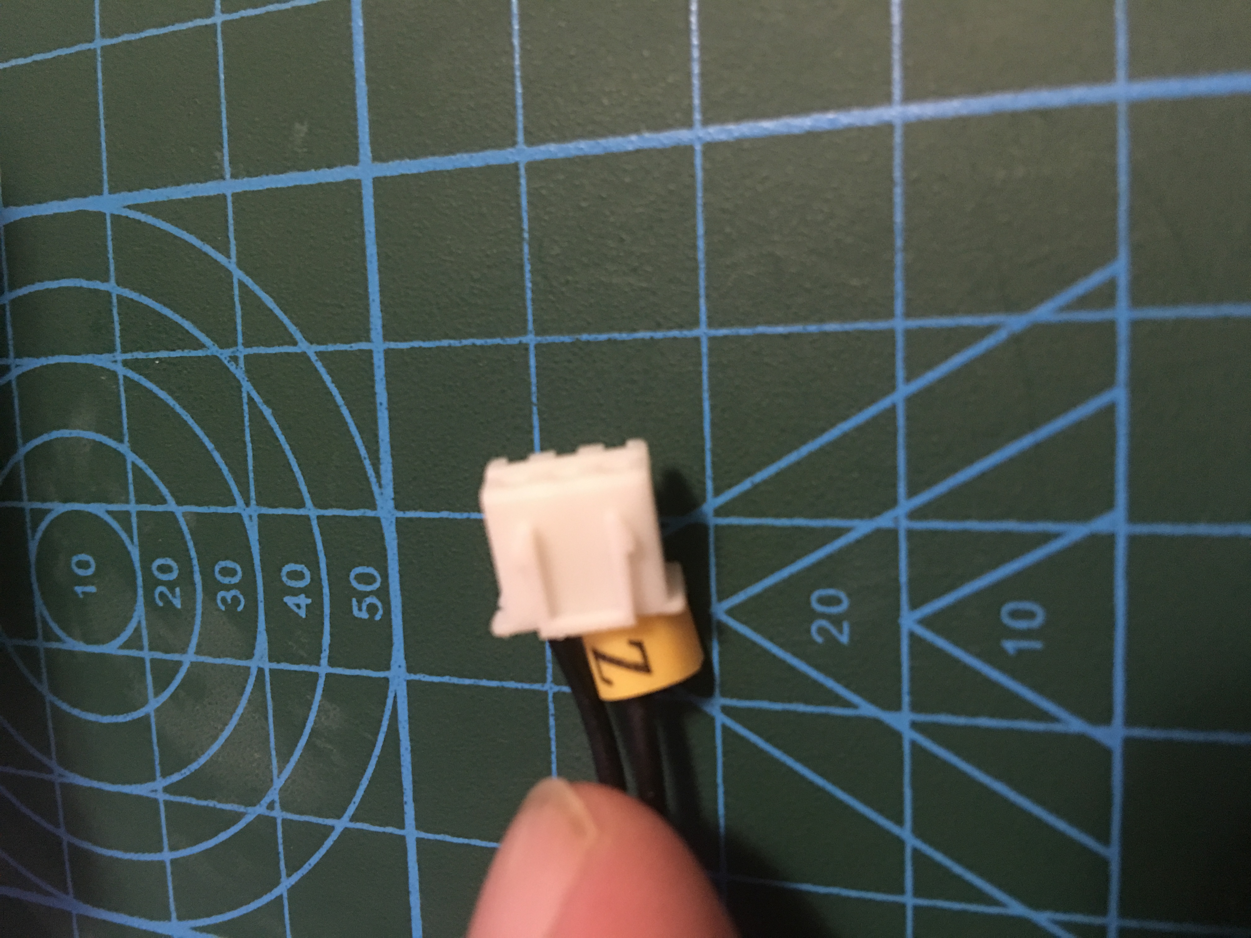
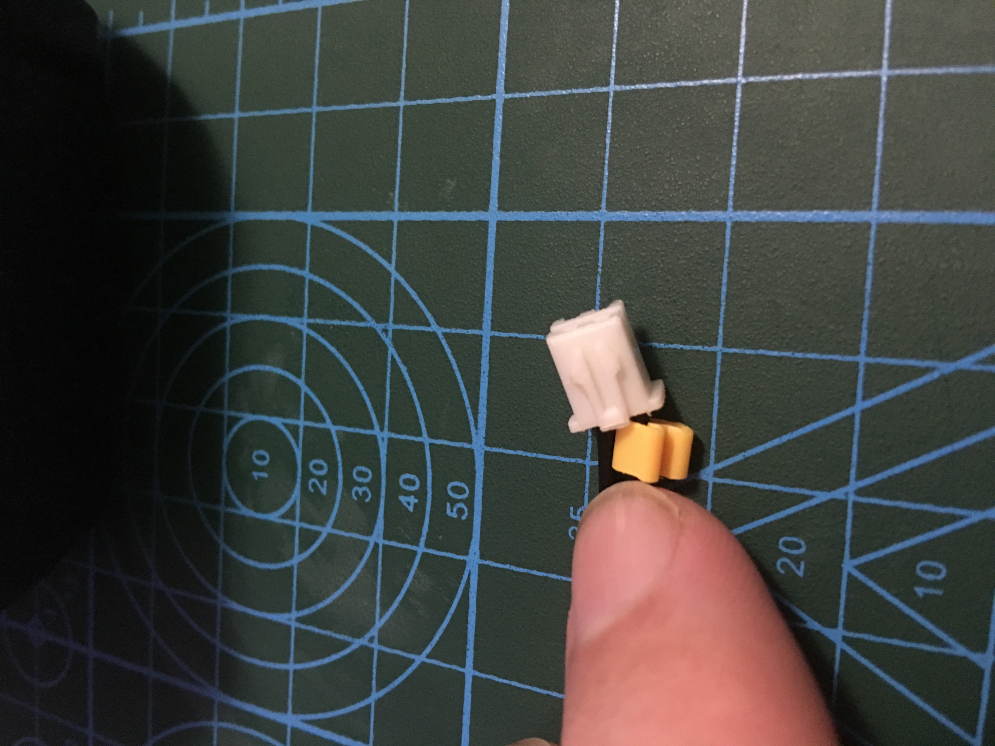
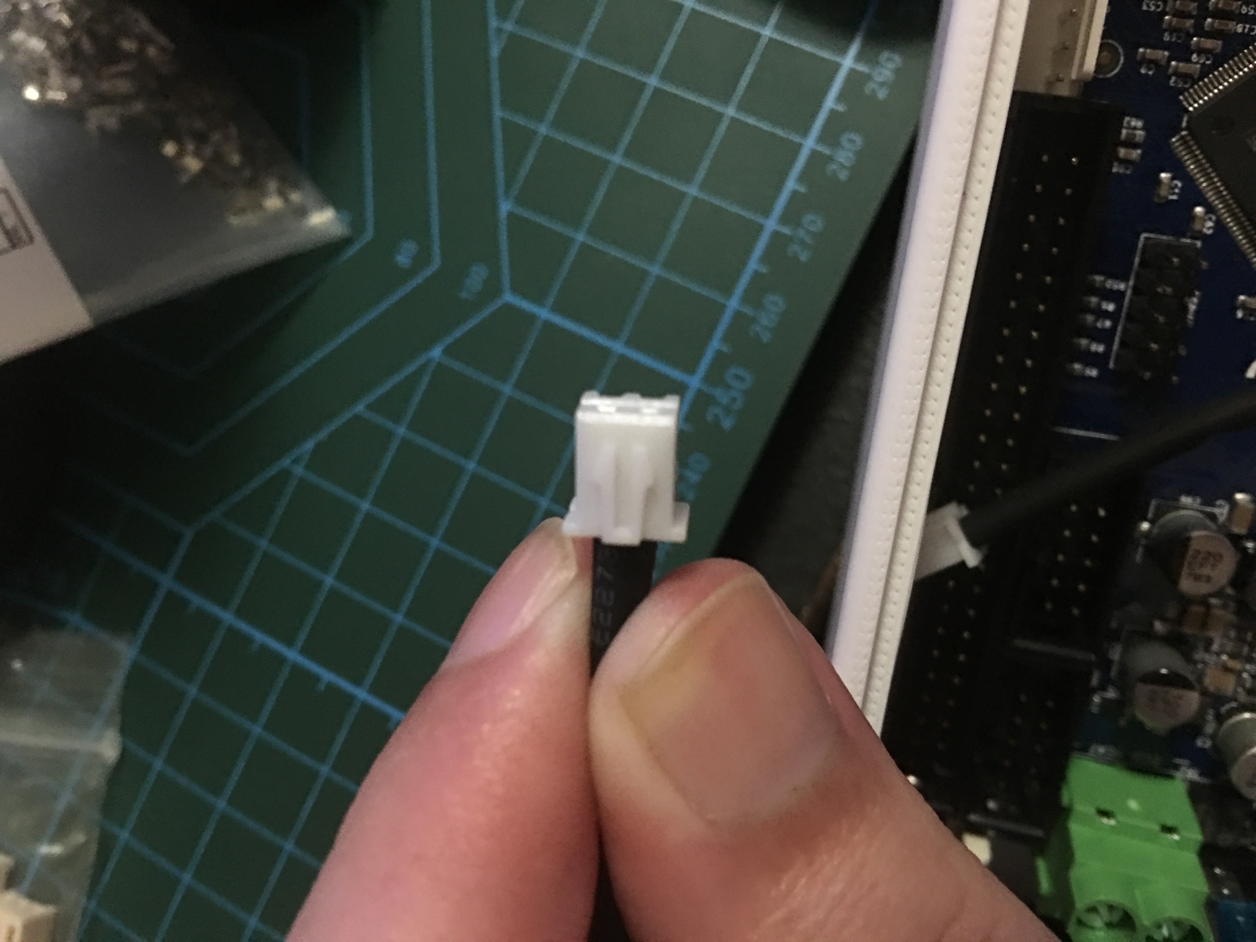
Anyone know of a guide so I can find what connectors my current cables use as well? I'm adding a few photos that may help. The first2 are examples of the connectors that my ender 3 uses for all it's electronics after that is a fan connector for one of the fans I bought.


-
they are jst-xh connectors
you just solder wires to the female one and put a heatshrink over the solder job.
-
@dwfl89 said in Question about using existing and some new parts with duet 2:
Anyone know the wording I should use to find some of these male connectors I am talking about?
Pictures didn't upload properly btw, so I'm just going off the other guy saying they're JST-XH conenctors. Male housing and pins cost much more than male headers. You might find cheaper if you shop around. But if the move is permanent, just cut off the old XH connectors and crimp on the new ones.
-
Edited & updated my last post so photos show.
@Veti So the connectors I want are jst-xh connectors to extend a few short cables.
@bearer I plan to just do that for most of the cables replace the connector on the end but a couple are super short so I figured making a extension cable for them may be easier,
-
Definitively XH connectors, 2pin and 3pin. Link I posted will give you male connectors that fit. (Buying male headers for pcb mounting and soldering wires to them is cheaper though)
-
Would it be ok to use tinned copper wire? A lot of the top amazon hits when I am looking for 24 and 16 awg wire is tinned copper. I want to say 90% of them... I hear they can cause shorts because tin flows under pressure or does this only apply if you tin the end of the wires yourself?
-
tinned copper wire means each strand is plated with tin, this is fine, they do it to improve corrosion resistance.
when tinned wires are refered to as bad its when you apply soldering tin to the ends before inserting in screw terminals, that can come loose.