CONN_LCD wiring for external driver
-
It depends on whether the 3.3V low current outputs on CONN_LCD are sufficient for your external driver. If they are:
- Pul+ to the Step output
- Dir+ to the Dir output
- Pul- and Step- to ground
- If Ena is an enable input, then Ena+ to +3.3V and Ena- to the Enable output. But on some drivers it is really a Disable input; in which case, Ena+ to the Enable output and Ena- to ground.
If your drivers need more drive, then someone published a level shifting circuit on this forum not long ago.
-
Thank you so much, I've done the wiring as instructed, stepper getting locked but not moving, sharing the Gcode , am I doing anything wrong, pls guide
; Configuration file for Duet WiFi (firmware version 1.21)
; executed by the firmware on start-up
;
; generated by RepRapFirmware Configuration Tool v2 on Fri Jun 21 2019 17:25:23 GMT+0530 (IST); General preferences
G90 ; Send absolute coordinates...
M83 ; ...but relative extruder moves; Network
M550 P"BIG FACTORY" ; Set machine name
M551 P"3m3d" ; Set password
M552 S1 ; Enable network
M587 S"MMM" P"KINGS1234" ; Configure access point. You can delete this line once connected
M586 P0 S1 ; Enable HTTP
M586 P1 S1 ; Enable FTP
M586 P2 S0 ; Disable Telnet
M584 X5 Y6 Z7 U10 E3:4 ; create the U axis and assign stepper driver 10 to it
; Drives
M569 P5 S1 ; Physical drive 5 goes forwards
M569 P5 R1 T2.5:4:5:0
M569 P6 S1
M569 P6 R1 T2.5:4:5:0 ; Physical drive 6 goes forwards
M569 P7 S1
M569 P7 R1 T2.5:4:5:0 ; Physical drive 7 goes forwards
M569 P3 S1 ; Physical drive 3 goes forwards
M569 P4 S1 ; Physical drive 4 goes forwards
M569 P10 S1
M569 P10 R1 T2.5:4:5:0 ; Physical drive 10 goes forwards
M584 X5 Y6 Z7 U10 E3:4 ; Apply custom drive mapping
M350 X32 Y32 Z32 U32 E32:32 I0 ; Configure microstepping without interpolation
M92 X80.00 Y80.00 Z4000.00 U80.00 E420.00:420.00 ; Set steps per mm
M566 X900.00 Y900.00 Z12.00 U900.00 E120.00:120.00 ; Set maximum instantaneous speed changes (mm/min)
M203 X6000.00 Y6000.00 Z180.00 U6000.00 E1200.00:1200.00 ; Set maximum speeds (mm/min)
M201 X500.00 Y500.00 Z20.00 U500.00 E250.00:250.00 ; Set accelerations (mm/s^2)
M906 X800.00 Y800.00 Z800.00 U800.00 E800.00:800.00 I30 ; Set motor currents (mA) and motor idle factor in per cent
M84 S30 ; Set idle timeout; Axis Limits
M208 X1800 Y1200 U1850 Z1800 ; Set axis maxima
M208 X-50 Y0 U0 Z-0.2 S1 ; Set axis minimum (adjust to make X=0 and Y=0 the edge of the bed); Endstops
M574 X1 Y1 Z0 U2 S1 ; Set endstop configuration (X and Y endstops at low end, U endstop at high end, active high, no Z endstop); Z-Probe
M307 H7 A-1 C-1 D-1 ; Disable heater on PWM channel for BLTouch
M280 P7 S10 I0
M558 P9 H7 F120 T6000 ; Set Z probe type to bltouch and the dive height + speeds
G31 P500 X50 Y0 Z2.5 ; Set Z probe trigger value, offset and trigger height
M557 X15:6 Y15:1190 S100 ; Define mesh grid; Heaters
M141 H4 ; Assign chamber heater to heater 4
M305 P4 T100000 B4138 R4700 ; Set thermistor + ADC parameters for heater 4
M143 H4 S100 ; Set temperature limit for heater 4 to 100C
M305 P0 T100000 B4138 R4700 ; Set thermistor + ADC parameters for heater 0
M143 H0 S120 ; Set temperature limit for heater 0 to 120C
M305 P1 X200 ; Configure PT100 for heater 1
M143 H1 S500 ; Set temperature limit for heater 1 to 500C
M305 P2 X201 ; Configure PT100 for heater 2
M143 H2 S500 ; Set temperature limit for heater 2 to 500C; Fans
M106 P0 S0 I0 F500 H T45 ; Set fan 0 value, PWM signal inversion and frequency. Thermostatic control is turned on
M106 P1 S1 I0 F500 H1 T45 ; Set fan 1 value, PWM signal inversion and frequency. Thermostatic control is turned on
M106 P2 S1 I0 F500 H2 T45 ; Set fan 2 value, PWM signal inversion and frequency. Thermostatic control is turned on; Tools
M563 P0 S"FIRST" D0 H1 F0 ; Define tool 0
G10 P0 X0 Y0 Z0 ; Set tool 0 axis offsets
G10 P0 R0 S0 ; Set initial tool 0 active and standby temperatures to 0C
M563 P1 S"SECOND" D1 H2 X3 F2 ; Define tool 1
G10 P1 Y0 U0 Z0 S0 R0 ; set tool 1 offsets and temperatures
M563 P2 S"MIXED" D0:1 H1:2 X0:3 F0:2 ; tool 2 uses both extruders, hot end heaters and fans, and maps X to both X and UG10 P2 X0 Y0 Z0 ; Set tool 2 axis offsets
G10 P2 X500 Y0 U-500 S0 R0 ; set tool offsets and temperatures
M567 P2 E1:1 ; set mix ratio 100% on both extruders; Automatic power saving
M911 S10 R11 P"M913 X0 Y0 G91 M83 G1 Z3 E-5 F1000" ; Set voltage thresholds and actions to run on power loss; Custom settings are not configured
; Miscellaneous
M501 ; Load saved parameters from non-volatile memory -
@milan said in CONN_LCD wiring for external driver:
M305 P4 T100000 B4138 R4700 ; Set thermistor + ADC parameters for heater 4
M305 P0 T100000 B4138 R4700 ; Set thermistor + ADC parameters for heater 0B4138 is the default value in the web ui and most likely not correct for your thermistors. An incorrect thermistor setting will report the wrong temperature.
-
@milan said in CONN_LCD wiring for external driver:
I've done the wiring as instructed, stepper getting locked but not moving
Can you confirm that the stepper is initially not locked, but it locks when you first try to move it and then remains locked until you reset the Duet or send M18?
If so, try increasing the T2.5 on the M569 P10 command. With only 3.3V drive, the step pulse may need to be a little longer.
-
Its locked from the beginning and remain locked till switch off, I've tried increasing the T2.5 to till T5, but no change , the stepper getting lil warmer , other than that no change happening, pls help
-
My guess is that the Enable input of your driver is actually a Disable input, and that the CONN_LCD outputs don't provide sufficient drive to your stepper drivers.
-
In that case, what could be the solution - Can I remap E0 to U and CONN_LCD pins to E0 (so that I can have Nema17 connected to CONN_LCD for extruder 0 - will this work -or please suggest the alternative to run this system
-
See https://forum.duet3d.com/topic/9683/additional-stepper-drivers-on-duex-5 for a suggested buffer circuit between CONN_LCD and external drivers.
-
dc42 ADMINISTRATORS 6 Apr 2019, 15:01
For a 74HCT365 or 74HCT367 (either will do) in 16-pin DIL package:
Pins 1,8,15 - ground
Pin 16 - +5V
Pins 2,4,6,10,12,14 - inputs from CONN_LCD
Pins 3,5,7,9,11,13 - +outputs to stepper driver +input pins (connect the -input pins of the stepper driver to ground)Also connect a 0.1uf capacitor between pin 16 and ground.
A few stepper drivers have a common +input pin. For those, use a 74HCT366 or 74HCT368 instead, connect the driver -input pins to the outputs of the chip (pins 3,5 etc.), and connect the common +input of the driver to +5V.
Take great care not to short +5V to any of the other pins on CONN_LCD.
HTH David
I've done the level shifting circuit, one clarification required,
Pins 2,4,6,10,12,14 - inputs from CONN_LCD
Pins 3,5,7,9,11,13 - +outputs to stepper driver +input pins (connect the -input pins of the stepper driver to ground)
Which means, should I connect 2,4,6 to Driver Pulse+, DIR+, ENA+
10, 12, 14 to Pulse-, DIR-, ENA- respectively? -
Here is a pinout diagram of the 74HCT365:
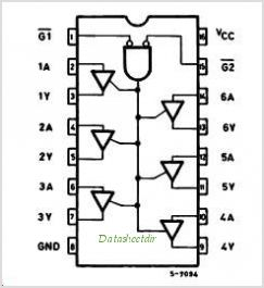
Connect /G1, /G2 and GND to ground, and connect Vcc to +5V. For the rest, pins 2 and 3 are one input/output pair, 4 and 5 are another, and so on. So here is one possible connection scheme, for one external driver:
STEP_10 from CONN_LCD to pin 2 (1A)
DIR_10 from CONN_LCD to pin 4 (2A)
EN_10 from CONN_LCD to pin 6 (3A)Pin 3 (1Y) to STEP+ on external driver
Pin 5 (2Y) to DIR+ on external driver
Pin 7 (3Y) to ENA+ on external driver
STEP-, DIR- and ENA- from external driver to GND.You can use the A and Y pins on the other side of the chip in a similar way for a 2nd external driver.
-
Thank You so much David, I wonder how could you mange to provide solution for every problem worldwide... Thank you once again , I'll connect as instructed..
-
Thank you so much, Its working flawlessly ...help me with endstop connectivity for this channel 10
-
@milan said in CONN_LCD wiring for external driver:
Thank you so much, Its working flawlessly ...help me with endstop connectivity for this channel 10
What endstop connectivity problem do you have?
-
Should we use Stop 10 Enc_B and Gnd for channel 10 Endstop?
Do we need to remap the other endstops in firmware as we do for Axis remap, we are using channel 5,6&7 for XYZ. Thanks
-
In firmware 2.03 and earlier, when you create axes the endstop inputs are allocated automatically. So if you create axes U and V in your M584 command then U will use the E0 input and V will use the E1 input.
In firmware 3.0 beta you have to allocate endstops for additional axes and specify the input pins using M574.