Duet3D Logo Duet3D
    • Tags
    • Documentation
    • Order
    • Register
    • Login

    CONN_LCD wiring for external driver

    Scheduled Pinned Locked Moved
    Duet Hardware and wiring
    3
    16
    1.0k
    Loading More Posts
    • Oldest to Newest
    • Newest to Oldest
    • Most Votes
    Reply
    • Reply as topic
    Log in to reply
    This topic has been deleted. Only users with topic management privileges can see it.
    • Vetiundefined
      Veti
      last edited by

      @milan said in CONN_LCD wiring for external driver:

      M305 P4 T100000 B4138 R4700 ; Set thermistor + ADC parameters for heater 4
      M305 P0 T100000 B4138 R4700 ; Set thermistor + ADC parameters for heater 0

      B4138 is the default value in the web ui and most likely not correct for your thermistors. An incorrect thermistor setting will report the wrong temperature.

      1 Reply Last reply Reply Quote 0
      • dc42undefined
        dc42 administrators @Milan
        last edited by dc42

        @milan said in CONN_LCD wiring for external driver:

        I've done the wiring as instructed, stepper getting locked but not moving

        Can you confirm that the stepper is initially not locked, but it locks when you first try to move it and then remains locked until you reset the Duet or send M18?

        If so, try increasing the T2.5 on the M569 P10 command. With only 3.3V drive, the step pulse may need to be a little longer.

        Duet WiFi hardware designer and firmware engineer
        Please do not ask me for Duet support via PM or email, use the forum
        http://www.escher3d.com, https://miscsolutions.wordpress.com

        1 Reply Last reply Reply Quote 0
        • Milanundefined
          Milan
          last edited by

          Its locked from the beginning and remain locked till switch off, I've tried increasing the T2.5 to till T5, but no change , the stepper getting lil warmer , other than that no change happening, pls help

          1 Reply Last reply Reply Quote 0
          • dc42undefined
            dc42 administrators
            last edited by

            My guess is that the Enable input of your driver is actually a Disable input, and that the CONN_LCD outputs don't provide sufficient drive to your stepper drivers.

            Duet WiFi hardware designer and firmware engineer
            Please do not ask me for Duet support via PM or email, use the forum
            http://www.escher3d.com, https://miscsolutions.wordpress.com

            1 Reply Last reply Reply Quote 0
            • Milanundefined
              Milan
              last edited by

              In that case, what could be the solution - Can I remap E0 to U and CONN_LCD pins to E0 (so that I can have Nema17 connected to CONN_LCD for extruder 0 - will this work -or please suggest the alternative to run this system

              1 Reply Last reply Reply Quote 0
              • dc42undefined
                dc42 administrators
                last edited by

                See https://forum.duet3d.com/topic/9683/additional-stepper-drivers-on-duex-5 for a suggested buffer circuit between CONN_LCD and external drivers.

                Duet WiFi hardware designer and firmware engineer
                Please do not ask me for Duet support via PM or email, use the forum
                http://www.escher3d.com, https://miscsolutions.wordpress.com

                1 Reply Last reply Reply Quote 0
                • Milanundefined
                  Milan
                  last edited by

                  dc42 ADMINISTRATORS 6 Apr 2019, 15:01

                  For a 74HCT365 or 74HCT367 (either will do) in 16-pin DIL package:

                  Pins 1,8,15 - ground
                  Pin 16 - +5V
                  Pins 2,4,6,10,12,14 - inputs from CONN_LCD
                  Pins 3,5,7,9,11,13 - +outputs to stepper driver +input pins (connect the -input pins of the stepper driver to ground)

                  Also connect a 0.1uf capacitor between pin 16 and ground.

                  A few stepper drivers have a common +input pin. For those, use a 74HCT366 or 74HCT368 instead, connect the driver -input pins to the outputs of the chip (pins 3,5 etc.), and connect the common +input of the driver to +5V.

                  Take great care not to short +5V to any of the other pins on CONN_LCD.

                  HTH David

                  I've done the level shifting circuit, one clarification required,
                  Pins 2,4,6,10,12,14 - inputs from CONN_LCD
                  Pins 3,5,7,9,11,13 - +outputs to stepper driver +input pins (connect the -input pins of the stepper driver to ground)
                  Which means, should I connect 2,4,6 to Driver Pulse+, DIR+, ENA+
                  10, 12, 14 to Pulse-, DIR-, ENA- respectively?

                  1 Reply Last reply Reply Quote 0
                  • dc42undefined
                    dc42 administrators
                    last edited by dc42

                    Here is a pinout diagram of the 74HCT365:

                    0_1561545899888_0659b341-5d73-420e-825e-42a4ac1378e8-image.png

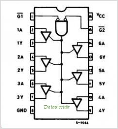
                    Connect /G1, /G2 and GND to ground, and connect Vcc to +5V. For the rest, pins 2 and 3 are one input/output pair, 4 and 5 are another, and so on. So here is one possible connection scheme, for one external driver:

                    STEP_10 from CONN_LCD to pin 2 (1A)
                    DIR_10 from CONN_LCD to pin 4 (2A)
                    EN_10 from CONN_LCD to pin 6 (3A)

                    Pin 3 (1Y) to STEP+ on external driver
                    Pin 5 (2Y) to DIR+ on external driver
                    Pin 7 (3Y) to ENA+ on external driver
                    STEP-, DIR- and ENA- from external driver to GND.

                    You can use the A and Y pins on the other side of the chip in a similar way for a 2nd external driver.

                    Duet WiFi hardware designer and firmware engineer
                    Please do not ask me for Duet support via PM or email, use the forum
                    http://www.escher3d.com, https://miscsolutions.wordpress.com

                    1 Reply Last reply Reply Quote 0
                    • Milanundefined
                      Milan
                      last edited by

                      Thank You so much David, I wonder how could you mange to provide solution for every problem worldwide... Thank you once again , I'll connect as instructed..

                      1 Reply Last reply Reply Quote 0
                      • Milanundefined
                        Milan
                        last edited by

                        Thank you so much, Its working flawlessly ...help me with endstop connectivity for this channel 10

                        dc42undefined 1 Reply Last reply Reply Quote 0
                        • dc42undefined
                          dc42 administrators @Milan
                          last edited by

                          @milan said in CONN_LCD wiring for external driver:

                          Thank you so much, Its working flawlessly ...help me with endstop connectivity for this channel 10

                          What endstop connectivity problem do you have?

                          Duet WiFi hardware designer and firmware engineer
                          Please do not ask me for Duet support via PM or email, use the forum
                          http://www.escher3d.com, https://miscsolutions.wordpress.com

                          1 Reply Last reply Reply Quote 0
                          • Milanundefined
                            Milan
                            last edited by

                            Should we use Stop 10 Enc_B and Gnd for channel 10 Endstop?

                            Do we need to remap the other endstops in firmware as we do for Axis remap, we are using channel 5,6&7 for XYZ. Thanks

                            dc42undefined 1 Reply Last reply Reply Quote 0
                            • dc42undefined
                              dc42 administrators @Milan
                              last edited by

                              In firmware 2.03 and earlier, when you create axes the endstop inputs are allocated automatically. So if you create axes U and V in your M584 command then U will use the E0 input and V will use the E1 input.

                              In firmware 3.0 beta you have to allocate endstops for additional axes and specify the input pins using M574.

                              Duet WiFi hardware designer and firmware engineer
                              Please do not ask me for Duet support via PM or email, use the forum
                              http://www.escher3d.com, https://miscsolutions.wordpress.com

                              1 Reply Last reply Reply Quote 0
                              • First post
                                Last post
                              Unless otherwise noted, all forum content is licensed under CC-BY-SA