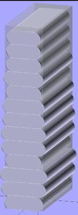
Uneven layers
-
@haggan90 A few random thoughts. That's a very small part to be printing with a large nozzle. As I said in your other thread, you need a lot of part cooling with large nozzles. The time to print that outer perimeter will vary depending on which bits of the "X" and "Y" it had to effectively miss. So the layer time will vary. Which means each layer will have more or less time to cool than subsequent layers. To test that theory, try printing the same part without the "X" and "Y" impressions. Better still, print a much larger cube to see if you still get the same effect.
-
Is your bed heater running in PID or in bang-bang mode? A bed heater running in bang-bang mode can cause layer banding.
The banding on the right hand one has a very obvious course pitch. Is it 3mm?
-
@dc42 David. The OP said above that he doesn't have a bed heater.
-
@dc42 No bed heather at the moment.
They have the same course pitch, and it's about 3mm apart on both.
The indents and outdents ar the same around the hole part.
I think it's like in the attached picture, and it occurs at the same height.
-
@deckingman Hi,
That's why I tried to print both with 0.405mm and 0.21mm, both at very low speed.
I tried a big vase as well with the same results. -
Does anyone have any other ideas?

I will try what @deckingman suggested and print a new larger cube without the X and Y imprints to see if the problem remains.Could this has to do with the 1066.67 steps/mm on the Z steppers?
Would it be better if I geared them down 1:3 to get an even 3200 steps/mm?
Or maybe remove the lead screws and add belts instead? -
what kind of lead screws are they?
-
@veti Hi Veti,
I bought them at Dold Mechatronik.
12x3mmhttps://www.dold-mechatronik.de/navi.php?a=45805&lang=eng
They should be of high quality.
-
i looked at the dold ones, but most of them were very uncommon.
i went with a SFU1204-DM like https://www.dold-mechatronik.de/navi.php?a=58147&lang=eng in the end. same diameter but 4mm lead. -
@veti Yeah I know, but if I would to go with the ball circulating screws it would cost me >300€ =/
-
yeah dold is quite expensive.
have a look at robotdigg
https://www.robotdigg.com/product/614/1204-Ball-Screw-with-standard-Machined-Ends -
@veti I need 3 pcs and they need to be 840mm long.
This has to be a last resort as I first want to figure out if I can solve it with the installation I got for now.
There shouldn't be any problems with the ball screws I have, they are straight. -
@deckingman here's a new test with a 50x50 cube and 0.6mm layer height. Same results.

-
how are your bearings on your z axis. do they move freely when you take off the lead screw? I had one of 4 of my bearings that was not as smooth at the others and it caused a similar issue.
-
And here's the same print with 0.3mm layer height.

-
@antlestxp Hi,
Yes they move very freely.
In my opinion it can't be any misalignment issue, as the indents/outdents goes all around the print (it's very clear on the 0.3mm picture) -
@haggan90 in my case the bearing would reduce bed movement every few mm causing the layers to squish until the bearing pushed through its "tight" spot
-
@haggan90 said in Uneven layers:
Does anyone have any other ideas?

I will try what @deckingman suggested and print a new larger cube without the X and Y imprints to see if the problem remains.Could this has to do with the 1066.67 steps/mm on the Z steppers?
Would it be better if I geared them down 1:3 to get an even 3200 steps/mm?
Or maybe remove the lead screws and add belts instead?measure the number of layers in the repeating pattern and then try a different layer height to see what impact it has. Those larger cubes without the X etc indentations make it easier to tie down the problem. It could be because you have non metric lead screws and the later heights don't add up to round numbers but if so this is pretty extreme banding for that.
-
@t3p3tony Tony,
We went through his lead screws and steps per mm etc in his other thread. His screws have a lead of 3mm which is unusual but means that one full step is 0.015mm. So providing he uses layer heights that are multiples of 0.015 then he should be using full steps and not relying on micro-stepping for positional accuracy. So 0.3mm layer height @1066.67 steps per mm @16X would be 320 micro steps or 20 full steps and 0.6mm layer height would equate to 40 full steps.
Even if the firmware rounds 1066.67 up to 1067 steps per mm then 0.3mm becomes 320.1 but you can't have 0.1 of a micro step so it would still send 320 (micro) steps. If the firmware keeps track of the fractional micro steps and adds one on when it gets to a full micro-step, then that would repeat at 3 mm but 1 micro-step is 1/10667 mm so that wouldn't be noticeable.
@Haggan90 Are you sure the lead of the screws is indeed 3mm and not say 1/8 inch? I only ask because 1/8 inch is 3.175 mm which might explain your banding if you set the steps per mm to 3mm. Clutching at straws here..........
-
@deckingman thanks, missed the other thread.
@Haggan90 worth trying the different layer height slices anyway, now you have the cubes printing well and seeing if the repeatability of the issue is the same or different.