Filament Sensor plus timelapse issue
-
@core3d-tech said in Filament Sensor plus timelapse issue:
The relay I'm using is this guy: https://www.amazon.com/gp/product/B01M0E6SQM
This relay module looks as a good choice, designed for 3.3V control signal, uses 3.3V supply, and has everything you need, including the flyback diode.
Where did you connect the VCC input to? (should be connected to the Duet's 3.3V rail, not to the output pin that controls the relay).
-
It is about current, not voltage. Per the photo those are Songle SRD-03VDC-SL-C relays. According to their datasheet, the part number specifies the lower current version, which requires 120mA to hold the coil. (The 'regular' relay is 150mA).
The processor on a Duet is an SAM4E8E, which per its datasheet can supply 30mA per GPIO pin (see page 1355) and 150mA across all GPIO pins combined (page 1354) as "absolute max" ratings.
In short, holding the coil in that relay demands about 4x what a single GPIO pin can supply... you are darn lucky you didn't fry that pin.
It also leaves 30mA for every other GPIO pin on the chip, combined, that are "logic high" at that moment. No surprise that some of those other pins couldn't keep themselves in their proper states.
To summarize: Quite rare to find a relay that a microprocessor pin can hold, directly, without the help of a transistor. Rule of thumb: Connect micro output pins to other solid-state circuitry (and even there, be aware of the current requirements); don't connect micro pins directly to physical things like relay coils, motors, etc.
-
This post is deleted! -
This post is deleted! -
@danal said in Filament Sensor plus timelapse issue:
It is about current
I believe that those modules include an opto coupler and a transistor which drives the coil. You can see the transistor at near the upper left corner of the relay in the pictures.
In other words, the duet's pin is not expected to provide the full current to drive the coil. That current comes from the VCC input which presumably is connected to the duet's 3.3V rail (presumably could also be fed with VCC = 5V).
I am using a similar one for VCC=24V, but removed the opto coupler and transistor and am driving the coil directly from E2 output ( (left the flyback diode on the board) . https://www.amazon.com/gp/product/B00LW2H5GC
-
@zapta said in Filament Sensor plus timelapse issue:
It was powered by the E0 end stop. I don't know (yet) where the Duet 3.3v rails starts and ends. Only the signal came from the CS5 pin. -
@core3d-tech , I think it's supposed to be connected like this
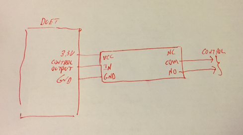
You need to make sure though that the duet 3.3V rail can provide sufficient current to drive that relay (~150ma according to https://www.banggood.com/SONGLE-Mini-3V-DC-Power-Relay-SRD3VDCSLC-PCB-Type-p-926636.html?cur_warehouse=CN ). Others may know if it's ok to do it.
-
The 3v3 regulator is good for 500mA (may need to check temperature ratings), but no idea how much of that the Duet needs for itself.
-
@zapta said in Filament Sensor plus timelapse issue:
I am using a similar one for VCC=24V, but removed the opto coupler and transistor and am driving the coil directly from E2 output ( (left the flyback diode on the board) . https://www.amazon.com/gp/product/B00LW2H5GC
Per the relay datasheet, a 24V version requires only 15mA. Will within the 30mA of which each SAM4E8E pin is capable.
.
Back to the original question, about the 3V version messing up the Filament sensor:
@zapta is correct, if wired like it shows in his post with the hand drawn diagram (and pull the jumper cap on the relay module), that relay module should work fine.
-

I'm only about 90% certain about removing the jumper... the documentation for the relay board is confusing.
