Building a DIY public domain low cost stepper motor analyzer
-
The analyzer, as primitive as it is now, already helped me diagnose a problem. I often had a general issue of under extrusion so the extruder path was clean and fully functional. Looking at the E steps counter on the analyzer while printing one of the problematic prints, I notices this:
As you can see, the retraction was significantly longer than the unretraction which results general trend of the filament going OUT of the extruder.
That also caused errors in the tracking of the stepper steps so it was easy to sync to that point of time with a scope and see this:
The unretraction steps are too fast compare to what a that stepper with 24V supply can handle which results in reduced and distorted current patter through the coils.
Looking at my config.g I found this line which sets the max extruder speed.
M203 X15000 Y15000 Z3000 E15000
And reducing it to E1500 solved the problem (the upper limit of reasonable stepper signal on my printer is about E2000). If my calculations are correct this is about 25mm/sec on my extruder with 0.9deg and 3:1 gear reduction.
Hopefully we will have one day analyzers that will do all this process automatically or even Duet itself since the coil currents are available to it (not sure how though how much information the existing TMC drivers convey to the CPU).
-
@zapta Thanks a lot for your interesting analysis. Please go on like this, I'm curious to see what else comes!
I try to minimize the vibrations of the hotend in my printer, so a vibration sensor coupled with your analysis could be interesting to find the best solution for configuration.
-
After further examination of my printer I realized that the insufficient current swing for fast extruder moves is probably caused by the very high inductance of the stepper I am using (~12mH) which prevents fast current changes through the coils.
I placed an order for a E3D pancake extruder which has ~2mH inductance
https://wiki.e3d-online.com/images/3/36/Slimline_Datasheet.pdf
In retrospect I should have spent more time reading this https://duet3d.dozuki.com/Wiki/Choosing_and_connecting_stepper_motors instead of installing arbitrary steppers. I was lucky though with X/Y and Z steppers, they are good
")
-
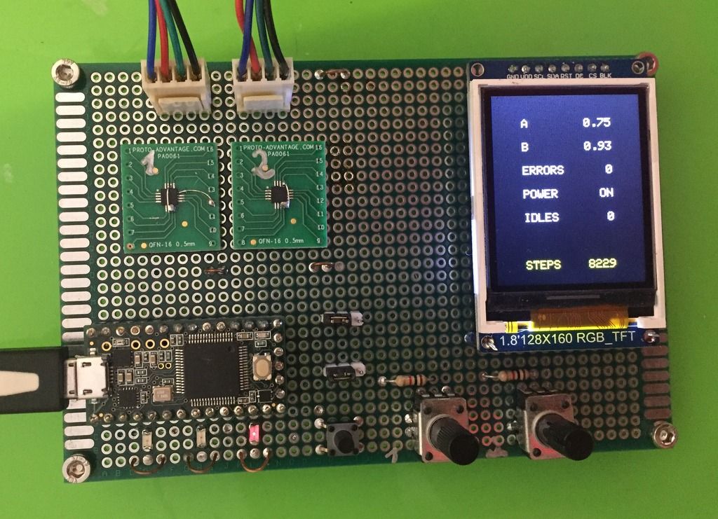
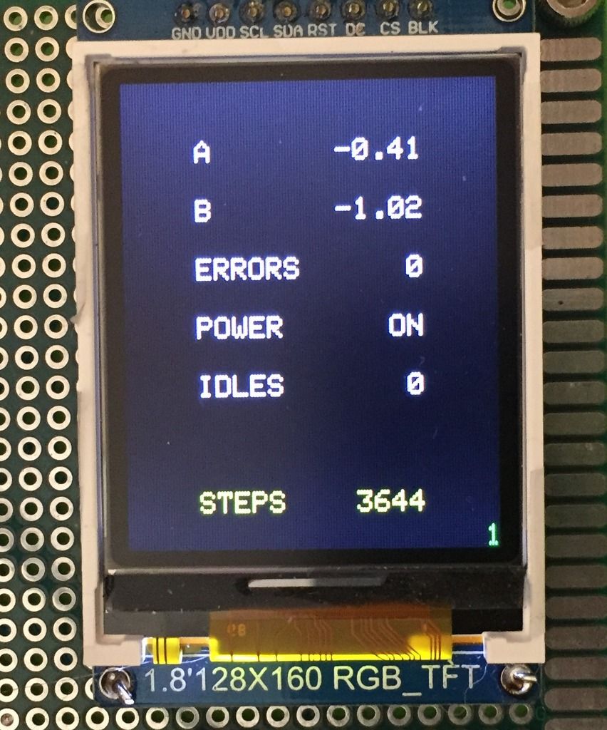
Had more progress with the analyzer's prototype. It now has a small display and shows information in real time. It shows current in both coils, number of quadrature state errors (e.g. if moving too fast for the stepper), the number of times the stepper was idle and the current step counter. Next I will try to show a graph on the display, of the step counter and/or of the coil currents. May also display aggregated values such as max current, RMS currents, speed, etc.
The prototype board with the display:
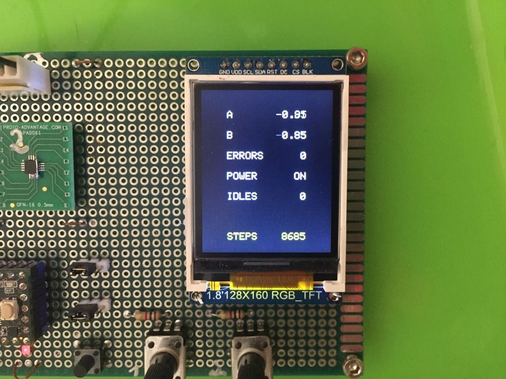
A close up of the display
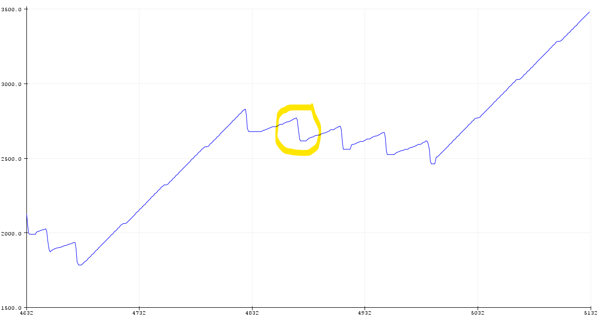
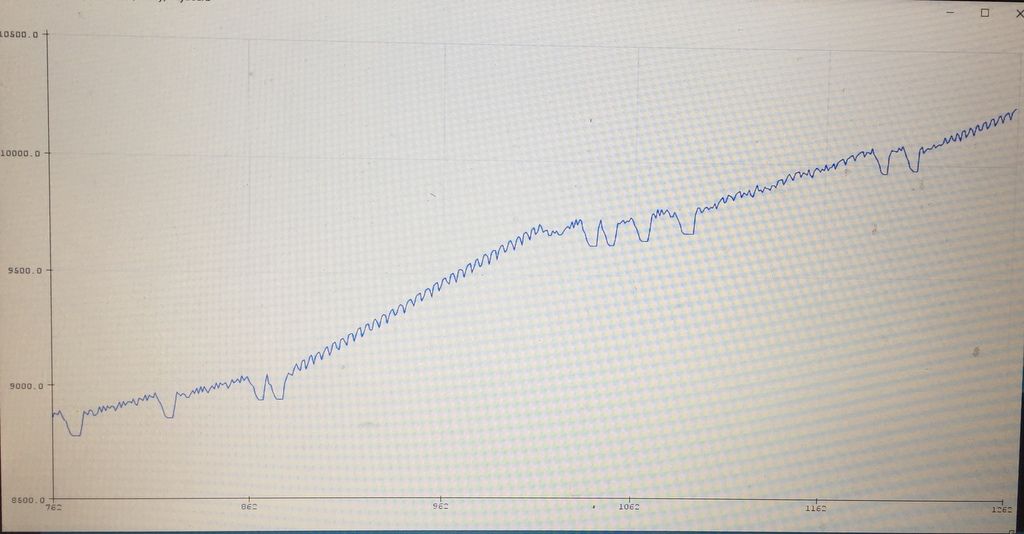
The data the analyzer sends in real time via the USB port is also plotted on the computer. This graph shows the extruder steps while printing Calicat. The big deeps are retractions. The ripples is the the pressure advance (set to 1.5).
-
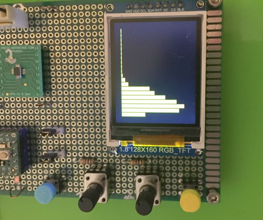
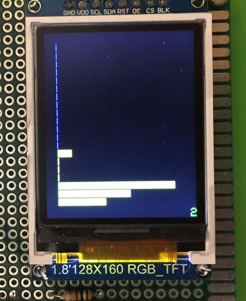
Implemented the first analysis screen, still crude but shouldn't be difficult to clean. It shows the histogram of the stepper speed. vertical axis is speed from 100 steps/sec (bottom) to 2000 steps/sec (top). The length of the bars is the relative time the stepper was at that speed.
This is the result of stepper A of a CoreXY printer while printing Calicat. The movements are relatively and the insufficient time to accelerate result in low overall speed:
This video shows it updated in real time while using PanelDue to move a few times 10mm (slow) and then a few times 100mm (fast):
https://www.dropbox.com/s/mw2pdjfm5h5n9b8/stepper_speed_histogram.MP4?dl=0
The blue button resets the histogram data when you want to start from scratch.
I believe that the Duet boards have sufficient information to provide such histograms. This could be another useful differentiator.
Next I will try to implement a similar histogram that show the peak current in each speed. I believe that this will be able to diagnose the problem I had with a high inductance extruder stepper as the bars will be significantly shorter for the higher speeds.
BTW, the microcontroller in the video is Teensy 4.0, a 600Mhz M7 beast that leaves a lot of room for future expansion, both in memory and computation.
-
Interesting.
I am still battling on with 12V on my current 'in progress' machine. I noticed similar issues with the commonly touted 3600 instant speed and 3600 max speed. I could hear it on my machine. Things got very rattly on retracts and things sounded so much better (clean tones) after I dropped the instant speed to 1100 and the speed to 2100.
If you paired up what you are building with something like the test on this you tube video you could have a very powerful tool.
https://www.youtube.com/watch?v=GVs2d-TOims
In a crude manned you could train a USB camera at the scales display and capture X number of frames around the point where the requested speed no longer matches the actual.
If you are looking at the current or voltage plots I would imagine it wouldn't be a huge stretch to investigate if the electrical characteristics of the motor indicate when the motor is about to stall. That said the effect of the current choppers may make things too muddied to see.
In relation to the retracts there could be an argument for two speeds on the retract. Unloading the filament could be really quick as the torque requirements are just about over coming the rotor and gear inertia (which in itself may indicate mass dampers would help avoid resonances) and then the true retract where you are looking to pull the filament back up away from the nozzle during which you have to overcome the viscosity of the material, but not pull a vacuum in the hotend which would encourage out gassing of the polymer.
-
@DocTrucker said in Building a DIY public domain low cost stepper motor analyzer:
I noticed similar issues with the commonly touted 3600 instant speed and 3600 max speed. I could hear it on my machine. Things got very rattly on retracts and things sounded so much better (clean tones) after I dropped the instant speed to 1100 and the speed to 2100.
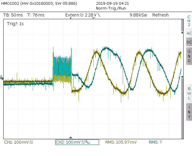
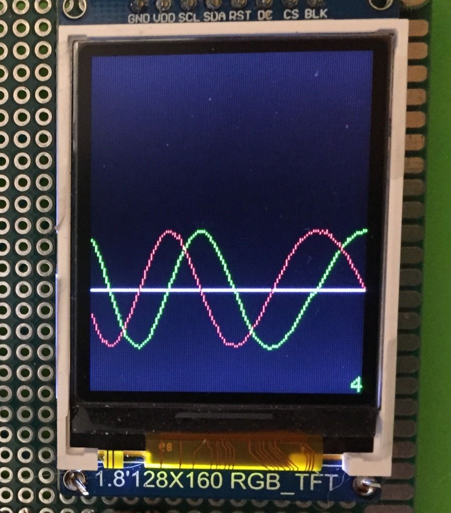
This is how the coils current look in a too-fast scenario
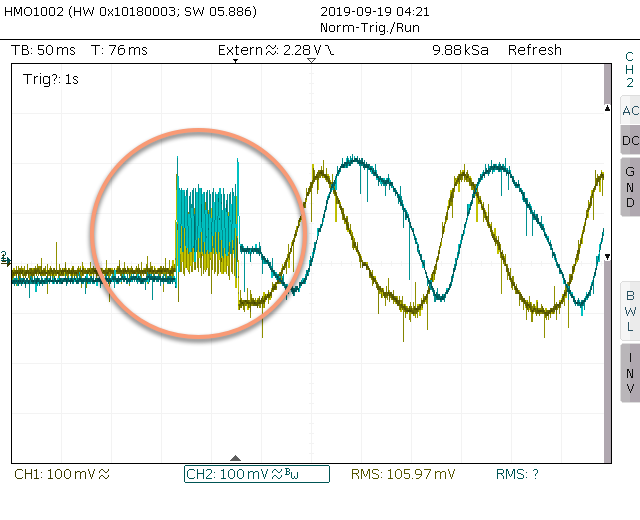
There is not enough time for the current to build up in the coils, the sine wave forms are distorted, the peek current are lower, and the torque level is ver low if at all. Currently the analyzer detects it by noticing invalid stepper phase errors and count them as bad steps. The current histogram by step speed will allow to diagnose it better and predict the max useful stepper speed. At lease I hope so
-
Just measured the extruder stepper (~26 full steps per mm) stepper speed histogram when printing Calicat with pressure advance of 1.0.
Majority of the time the speed is in the 100-200 full steps per sec range, with very short time going up to ~1800 full steps per sec (during retraction).
This suggests to me that the retraction speed has little affect on the overall print time.
-
Thank you for this thread! It really shows how a simple tool used with intelligence gives a lot of insight.
-
The firmware of the stepper analyzer proof of concept is done and the prototype has four functioning screens (see below) which demonstrate the viability of the hardware design. Next I will work on a PCB layout.
Screen1: general information in text form (current in coils A.B, total steps, phase errors, etc)
Screen2: histogram of time spent in each speed range (botton = slow, top = fast).
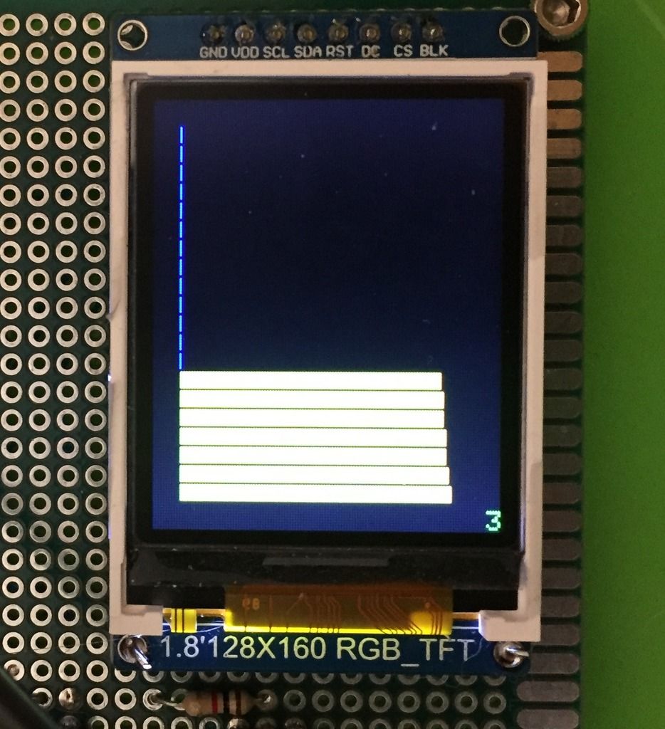
Screen3: histogram of coil current vs stepper speed. Will indicate issues such insufficient power voltage or too high inductance, which cause lower currents in high speeds.
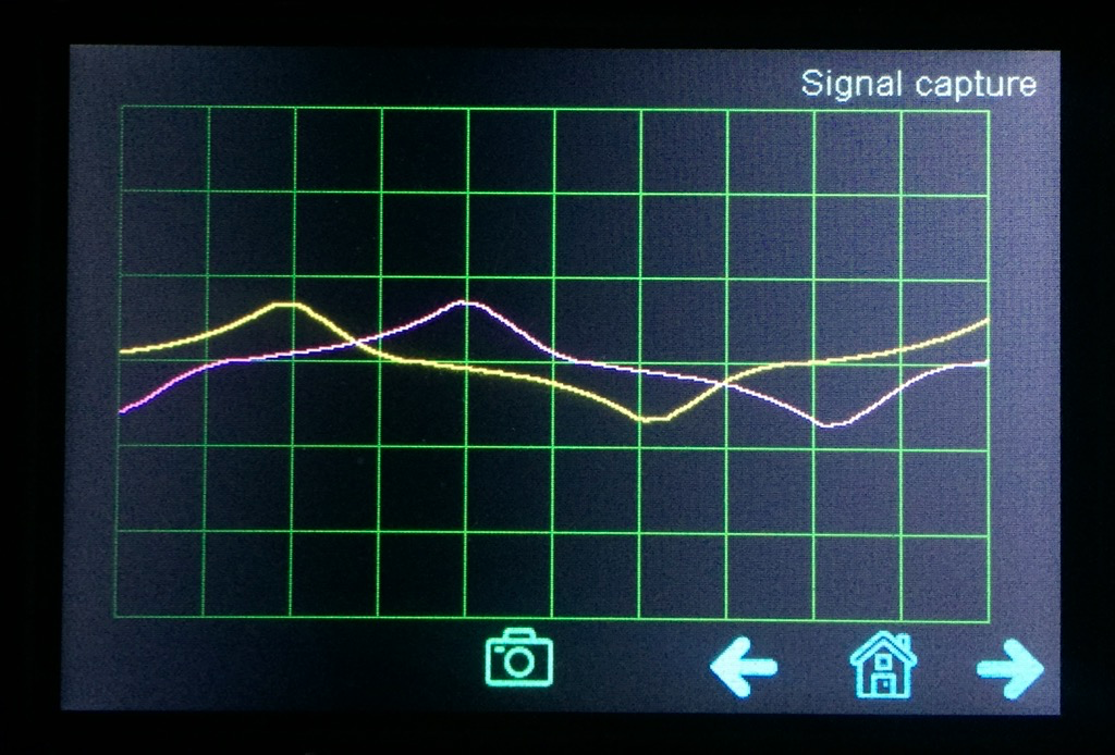
Screen4: general signal waveforms of coils A (green) and B (red).
-
Slowly slowly progressing with the stepper analyzer project. The PCB design is completed and I ordered it from a PCB house. Should arrive in a week or two. Snapshots of the schema and PCB are included below. The schema is straight forward, two current sensor, a Teensy 4.0 MCU module, small display, two buttons for user interaction and 4 dip switch for configuration (e.g. to reverse the step count direction). The dotted region includes optional stuff for firmware developers.
PCB Layout
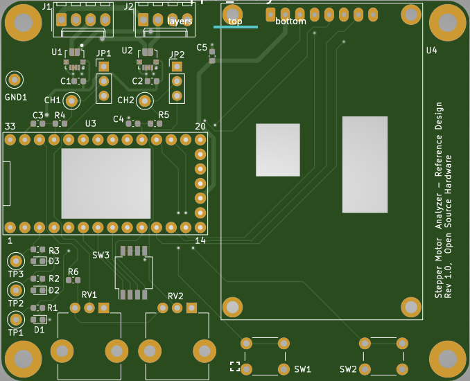
Schema
stepper_analyzer.pdf -
Nice work. I need to read through this in detail, forgive me if the following is already answered.
Does the detail of the plots change under acceleration vs deceleration? Any indication that lag or advance of the rotor may be delectable? I'm not talking about hundredths of a degree resolution, just and indication of where the rotor is relative to target on dynamic moves?
Running 3 P3Steel with Duet 2. Duet 3 on the shelf looking for a suitable machine. One first generation Duet in a Logo/Turtle style robot!
-
@zapta this is a great project! thanks for documenting it as you go through. Worth a submission to hackaday once complete I think!
-
Awesome project! Thanks for sharing!
-
This is neat. One time I thought of building a step motor dynamometer to compare motors by looking at their torque curves. I wish I followed through. Maybe that can be another module for this device?
-
This could be a good project for a electronic magazine (I mean as an article in the magazine with explanation): a useful topic for many users, nice images and a PCB project. Something like Elektor in germany.
-
@DocTrucker said in Building a DIY public domain low cost stepper motor analyzer:
Does the detail of the plots change under acceleration vs deceleration? Any indication that lag or advance of the rotor may be delectable?
Good question. I don't know. I clearly observed that the current does not reach full amplitude when the speed was too fast that voltage and stepper combination but I don't know if the current signals are sufficient to detect missing steps.
-
@T3P3Tony said in Building a DIY public domain low cost stepper motor analyzer:
@zapta this is a great project! thanks for documenting it as you go through. Worth a submission to hackaday once complete I think!
Hi Tony, yes I plan to do that, to get more awareness. My goal is to provide a baseline hardware and firmware such that more knowledgable and creative people can use to provide useful tools for the community.
-
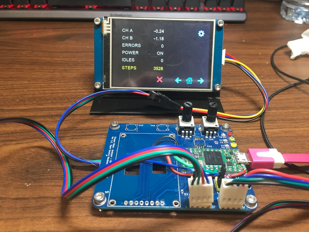
After procrastinating on this project for some time I realized that having to implement the UI with a low level screen API was distracting so I decided to switch to a smart touch display (Nextion 4.5") and things started to move fast. Here are a few pictures with the current state. Next I plan to redesign the PCB for the new LCD and clean up the UI.
The old PCB with connected to the new display:
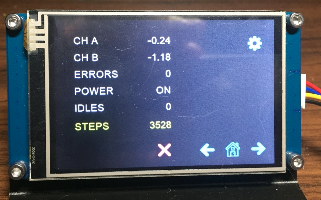
The home screen with summary data:
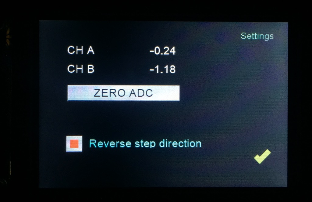
The setup screen. It allows to set the zero current and to reverse the steps direction.
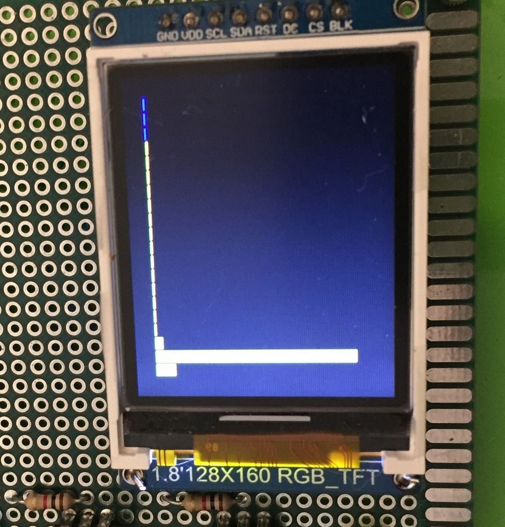
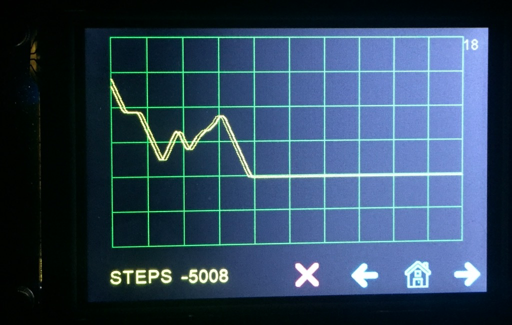
The distance graph. Graphs moves up/down in real time with the steps counter:
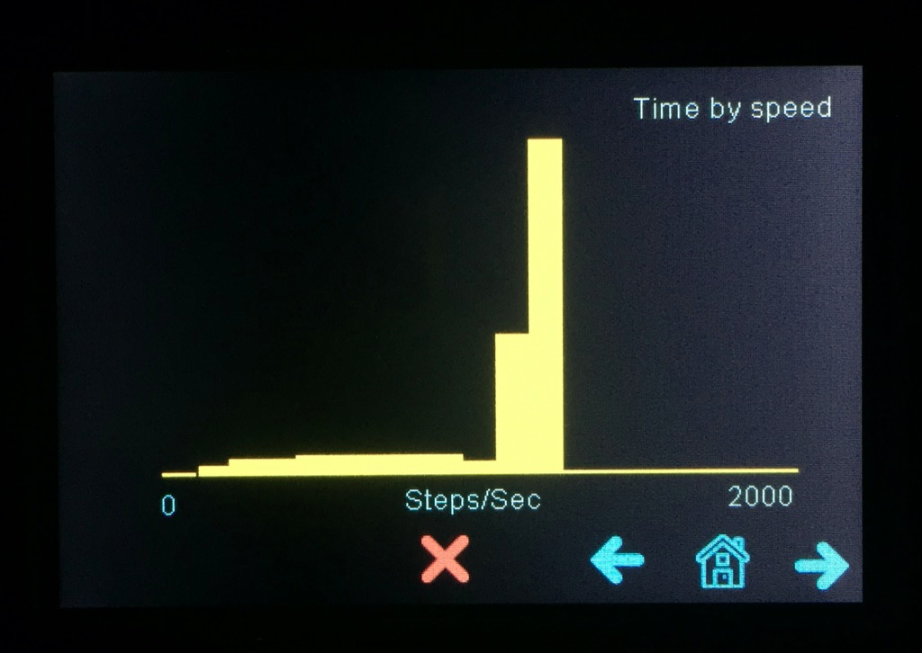
Histogram of time by speed. I am thinking adding a similar screen with histogram of distance by speed.
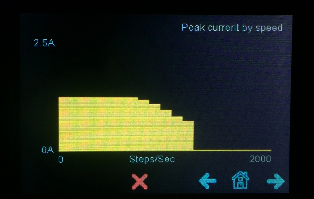
Histogram of peak current vs speed. In this example, a 12V 1.2A stepper, the max current starts to drop at ~7000 steps per sec.
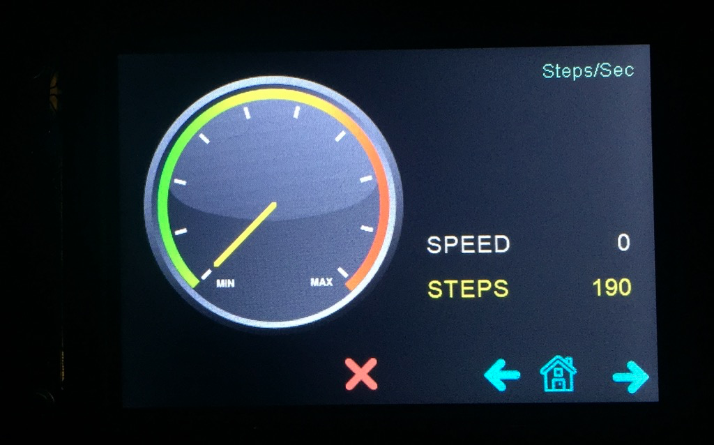
A tachometer that shows speed in real time.
A capture of the current signals in the two stepper coils. This one is at high speed with only 12V supply which resulted in poor current pattern, close to the speed limit of the system. (ideally the two signals should look like sine/cosine).
-
@zapta your project is very interesting. Can you tell me please whether you were able to analyse currents with microstepping and to which detail?
Thank you for pointing me to the ACS70331. I have a couple of ACS712, but they are much too slow.
I would like to analyze the correlation between step commands to the TMC, the created currents from TCM to stepper and the resulting movement of the stepper.