Duet 2 Wifi - Bed no longer heating
-
@EasyTarget said in Duet 2 Wifi - Bed no longer heating:
There are other things that could be tested, in particular the gate and source voltages of the mosfet to verify that it is receiving the gate signal, and that it's source is properly grounded.
How do I check that?
I don't think it's a wiring issue - it's been functioning fine for several months before failing. The wiring wasn't changed in that time. I've connected the bed to a different board and it works (using the same wiring and powersupply)
-
@EasyTarget If you measure the output at the terminals with a multimeter and no connected devices you should see V-input for a good working system at both pins. To the novice they may measure one pin to another and see 0V and think it's not working...
-
@3ddevil said in Duet 2 Wifi - Bed no longer heating:
It is the normal function of a heater mosfet output to show Vin on both pins when set to on and disconnected from a load (open). The multimeter has an internal load that is extremely small (1-10Mohm) compared to the driven circuit. You can measure the voltage at the pins when there is a load.
Correct, with no load both output pins will show Vin on a multimeter. The bed heater LED will pass Vin from the positive to the negative terminal.
As the MOSFET looks in good condition, first thing to check is whether the bed heater led turns on when you turn the bed heater on. If yes, it's a problem with the external wiring or the soldering of the terminal block. If no, check that there is 5V between the MOSFET gate and source pins when the heater is turned on, and 0V when off.
Duet WiFi hardware designer and firmware engineer
Please do not ask me for Duet support via PM or email, use the forum
http://www.escher3d.com, https://miscsolutions.wordpress.com -
@dc42 said in Duet 2 Wifi - Bed no longer heating:
The bed heater LED will pass Vin from the positive to the negative terminal.
Ah; I stand corrected, I hadn't realised the heater LED was on the output side rather than the gate of the mosfet, as they say; assumption is the mother of all friends. This does explain why it shines so brightly. I'd have put it on the gate, guess that's my novice nature, it is more sensible to put it on the driven side.
-
@Tarasque_1024 said in Duet 2 Wifi - Bed no longer heating:
How do I check that?
As @dc42 and @3ddevil correctly say, the fact the LED comes on (you say that in the OP) actually means the mosfet should be good.
Next step is to switch your multi-meter into resistance (continuity) mode and check each individual wire between the bed terminals. Eg from the +bed screw terminal to the + solder connection at the other end of the wire, same for the - wire.
If they conduct (zero resistance) this is good.
Next check the whole bed resistance; disconnect the bed wires from the terminals on the board and measure the resistance between them. It should be near zero; the heatbed has a resistance of one or two ohms, depending on capacity.- Try to do this with the bed and board in their normal place, wires can twist and internal breaks sometimes only happen when the wire is in one position, when you move it the wire strands touch inside the sheath again and it suddenly looks good again, until later.
- You must disconnect from the screw terminals first because the bed led and diode(d4) will always show a false 'good' reading if the wires are connected to the board!
==================
I'm going to post the image I'd hacked up earlier, if you or anybody else needs to check the mosfet it can serve as a handy reference:
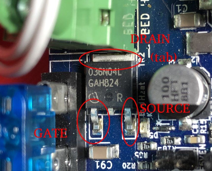
And here is the schematic of this bit of the system to add some context and because I really should have checked it earlier:
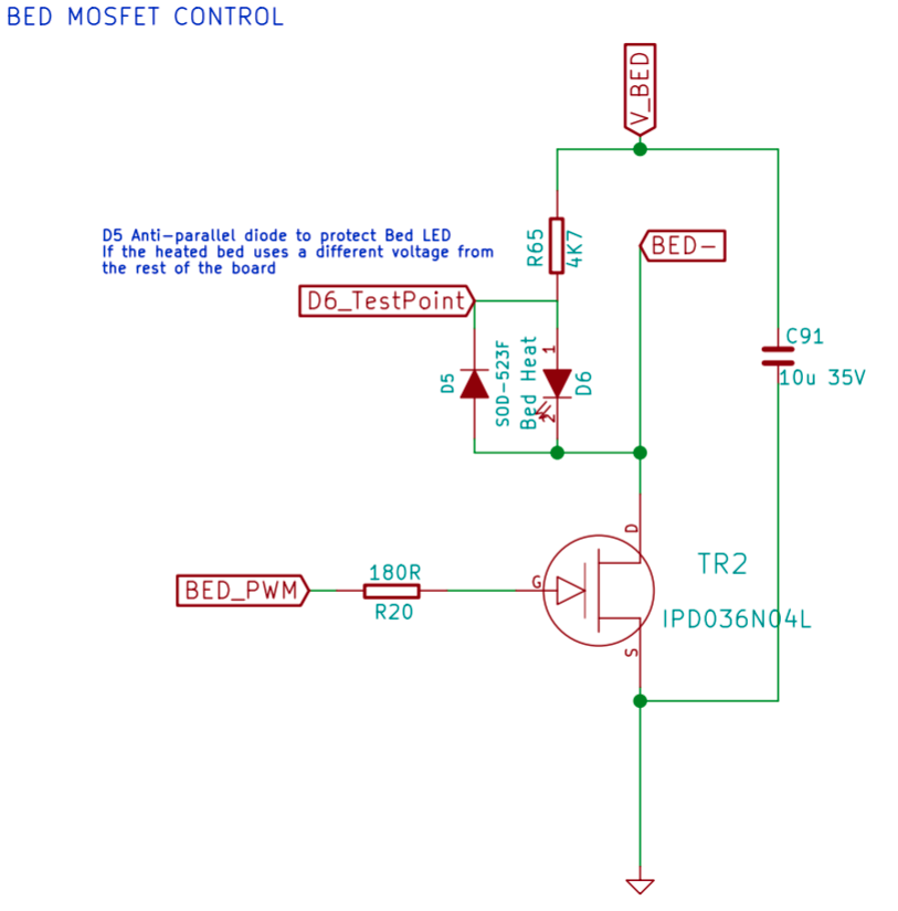
Finally; the spec sheet for the mosfet is here:
http://www.icbase.com/File/PDF/IFT/IFT03781303.pdfDisaster? The original Printeye is dying with RRF 3.5 (M208 depreciated).
PrintPy2024 to the rescue!
MicroPython based; with simple wiring and and no custom PCB. -
Does the underside of the Duet look OK? In particular, the soldering of the pins of the bed heater terminal block, and the traces to them.
Duet WiFi hardware designer and firmware engineer
Please do not ask me for Duet support via PM or email, use the forum
http://www.escher3d.com, https://miscsolutions.wordpress.com -
@dc42
I've taken the board out and turned it over to find this:

It looks the the Bed - pin of the screw terminal has failed. The 'corroded' pin popped off with a light touch and the terminal itself doesn't feel secure (flexes easily). There is a slight bubble there - likely due to heat from the short.

Looks like the screw terminal will need to be replaced, but the mosfet is likely to be ok?
-
@EasyTarget Thanks for the annoted pic. Will help with troubleshooting (should I have any issues in future)
-
@Tarasque_1024 said in Duet 2 Wifi - Bed no longer heating:
I've taken the board out and turned it over to find this:
Ouch! Yes, new connector time. The good news is that it is on the Drain, this is the heatsink tab of the mosfet and I believe the entire copper area around it studded with vias (the small plated through holes) is the heatsink area?? @dc42 knows the board better than anybody
")
- If so this means you, or whoever does the repair, has plenty of copper to connect to. The +ve connector looks good so it may be better to leave that undisturbed and cut the old connector in half and just replace the negative side.
- The huge heatsink area can make soldering tricky, it just refuses to heat up enough.. Flux and relatively low melting point solder are your friends there. It also explains why this joint wasn't properly formed in the first place.
- Finding one bad joint often means there might be others, though all the other joints I see in your pictures look good. If still in warranty you should consider that as the first option.
-
@Tarasque_1024 that is for sure the cause ...this was well diagnosed by everyone, ultimately you were patient and followed through...this community has learned more for it, so thanks.
From your pic looks irregular, hard to tell from photos but are there signs of rework?
Board manufacturing is complex and there are literally hundreds of steps and dozens of companies involved. Here I think the copper cladding has ripped it's adhesive off of the fiberglass, likely due to excessive force and/or bad soldering. It's possible this component was reworked during a factory test and the excess solder that seems to be there in the pic would cause thermal expansion/shrinkage that could start the delamination.
Ultimately it looks like the pad was stripped off and took the blue epoxy with it...which would happen due to a rocking motion and excess force.
...if so you can not rework this unless you are at least somewhat experienced. Proper rework would involve stripping and sanding the emulsion (blue epoxy) with a Dremel, not stripping the thin 37, micron copper layer all the way through and then prepping the surface for solder and preheating the entire board to something like 70C for proper flow. You also need to shape the solder area for good wetting and inspect to make sure none of the (+) pad area got damaged. If this doesn't intimidate you it is doable, could be educational and you don't have much to loose. I don't see it damaging systems nearby.
I do not think this finding reflects on other components on the board. Board through hole connections are hand soldered and larger pads always have this risk.
-
@3ddevil I have no idea about rework (or lack there of). The pin and solder are all crumbly - it took minimal pressure (with fingers) to convert into dust. I don't recall anything odd looking with the board when installing, although that was in January (so I might have forgotten). I'm sure I would have noticed if it looked like it did in the pics above - that doesn't look healthy at all.
-
I would mend it by removing the broken bit of copper pad, taking a piece of solid copper wire (e.g from UK 30A ring main cable), wrapping it around the terminal spill, and soldering the ends to the copper underneath the mosfet. As already mentioned, this will require a high power soldering iron with a large bit.