Add laser for duet2 wifi
-
Hi all
Finally My Laser has arrive
soI want to connect to My duet 2 Wifi
i tried to hook the cable and adjust the power then I burn the fan fuse luckly I have spear form old duet I burned before
so I said it's enough I don't want to burn second board again
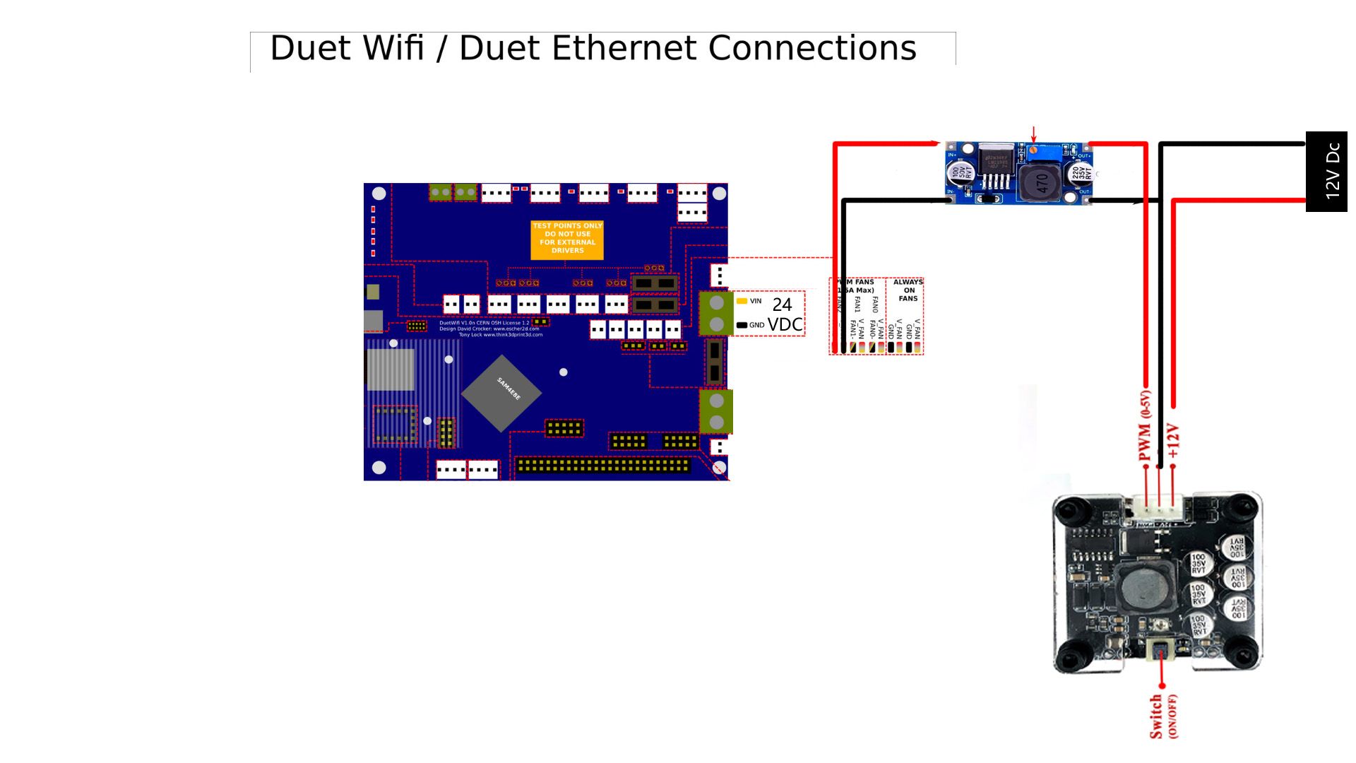
so I want to know it this diagram ok for connecting the Laser
My laser 15 W ( in fact it's only 8W )
setdown LM2596 dc-dcI want to step down the power form ( fan_2 ) 24 VDc to 5 Vdc to give the laser signal to power on or Off
-
No it wont.
12V external power == good.
buck converter on a 24V fan pin to a 5V pwm == bad.
Read: https://duet3d.dozuki.com/Wiki/Laser_PWM_control
I have a similar laser module (different looking controller board), mine seems to accept a 3.3v pwm input just fine. It has a analogue mode too where a 0-10V signal seems to be required. I've never used this.Disaster? The original Printeye is dying with RRF 3.5 (M208 depreciated).
PrintPy2024 to the rescue!
MicroPython based; with simple wiring and and no custom PCB. -
SO I have to make this PCB board ?
-
@EasyTarget
is it possible to use heater 6 PWM
-
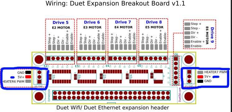
@yaman If you have one of the expansion break out boards then yes, they step the heater 6 and 7 PWM signals up from 3.3V to 5V using a 74HCT02
-
@yaman said in Add laser for duet2 wifi:
SO I have to make this PCB board ?
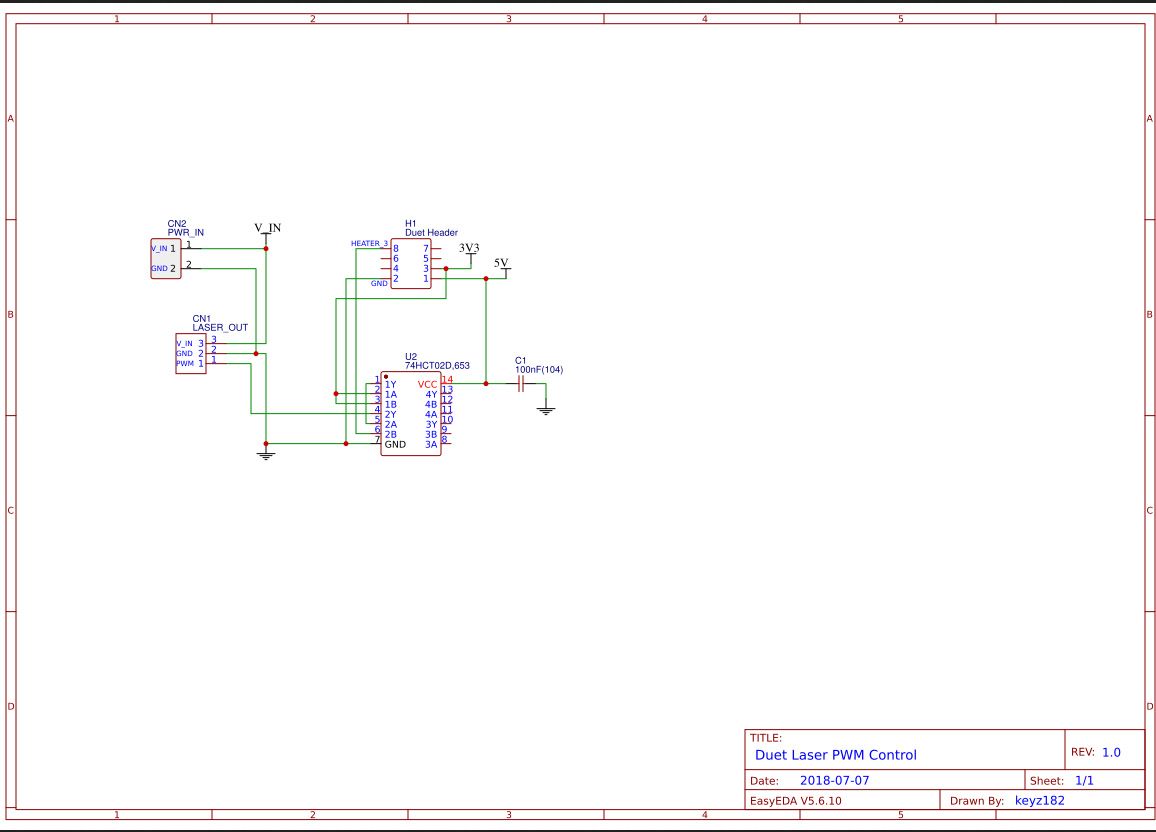
You can do, yes. Though possibly with less whitespace around it.
It's an idealised circuit, but it provides a clean 5v PWM signal to the laser, which is good and has an interlock to stop the laser blipping full power during powerup.is it possible to use heater 6 PWM
I dont know much about the expansion board. If it is a 5V signal then yes!
But if it is a 24v heater output, no.
Edit; looks good, thanks @T3P3TonyThe issue here is that common laser modules set their PWM line to 5V and expect the controller to then pull that to 0v for the off part of the PWM cycle. This 5V is enough to damage the Duet if you put it directly on a controller pin. You need some sort of buffer between the two.
In the circuit above this is done by the 74HCT020, which is a 5V logic chip, but will trigger with the 3v3 signal from the duet too. It's also fast and transmits a clean signal.
There are quite a few options, you can possibly get a circuit like the one above from aliexpress etc already. Though it's not a complex one to build if you know how. Another great option is an optoisolator. But you lose the 'blip' protection.
I'd suggest more research, try searching on more general topics like 'how do I control a 5V pwm laser module with a 3v3 controller', etc.
A 'hidden' advantage of the circuit above is that, unlike many transistor/mosfet pwm drives which have internal capacitance, the 74HC chip produces a very clean signal. for the laser. And this is an advantage for lasers like ours.
edit: Another great reason to use the expansion card solution..- once you have it working, try a fairly low PWM frequency (like 100 Hz. low) and 50% PWM cycle (power), this is when the 15/8W modules are 'pulse' cutting, you can do this continuously and get good results so long as your feedrate is slow (or you get a row of dots). There are a bunch of videos about this on youtube and elsewhere too, part of the secret is a clean PWM signal. I get good results, it's much more powerful at this sort of engraving than my 5W unit is at 100%.
Disaster? The original Printeye is dying with RRF 3.5 (M208 depreciated).
PrintPy2024 to the rescue!
MicroPython based; with simple wiring and and no custom PCB. -
@EasyTarget
thanks for your replay
I like to buy circuit then make one
I found everywhere I look this things
1- PWM Laser Power Output Regulator/Frequency&Duty Adjustable2-EleksMaker
 PWM To TTL Transition Module
My laser is PWM and TTL
so any suggestions ? -
@yaman said in Add laser for duet2 wifi:
I like to buy circuit then make one
I can appreciate that
")
I found everywhere I look this things
1- PWM Laser Power Output Regulator/Frequency&Duty AdjustableThis is not what you want. It is a standalone controller for when you are using the laser on a bench etc. It creates the PWM/ttl signal itself. The specs say it has a serial control (but I don't see that in the pictures) which could make it useful for some cnc stuff. But not for the Duet; serial control is nowhere near fast enough for our use.
This looks more like it! so long as it can be driven from a 3.3v input. The eleksmaker controller is 5v, but this adaptor might be fine with 3.3v too. If so, it looks like exactly what you want.
- its late here, I'll try and find time to look at this properly (find the circuit or something) before Monday.
- in the meantime here is a thread that may prove educational about this module:
https://github.com/openfab-lab/toolsDocs/issues/13
That is also good to know, it means the 'PWM pin should be properly driven both high and low (TTL PWM) for best results. Non TTL PWM only pulls the pin low, it has to be pulled back high by a resistor and for this reason can be a little bit less precise in timing; I've seen this discussed to death in CNC forums.
This explains things nicely too.so any suggestions ?
If you have money to burn, order one of those modules so that it is on the way.. I'm pretty sure it is a good plan but wont be held responsible if not.
PS: Nederlands?
open laser module TTL vs PWM #13
Disaster? The original Printeye is dying with RRF 3.5 (M208 depreciated).
PrintPy2024 to the rescue!
MicroPython based; with simple wiring and and no custom PCB. -
@EasyTarget said in Add laser for duet2 wifi:
Nederlands
-
@yaman Sorry for not getting back earlier, I still think this card will suit your needs.
I've just spent all week fitting a 32bit 3.3v controller to my cnc/laser rig (not a Duet, something based on a 7 Euro ESP32 NodeMCU module) , this and the above discussion has me a bit over-focused on laser driving from 3.3v. systems.
The laser on my upgraded rig is a 5.5W unit with a pure TTL input. I'm lucky, it can simply be wired to my controller directly; the float voltage on this pin (measured) is 3.27v, and it is high-impedance meaning it does not absorb or supply any real power, it simply follows the voltage. Switch on voltage is around 1.5V . I can simply connect this to the relevant pin of the ESP module.
I'm also going to put my 8/15W unit into a new machine with a big bed (fabric/leather cutting and decorating is the main goal) but have not worked out the specifics of this yet, it's somewhat low priority, and whatever I do will be a full custom solution. For your application I think a unit like you are getting is ideal.
Disaster? The original Printeye is dying with RRF 3.5 (M208 depreciated).
PrintPy2024 to the rescue!
MicroPython based; with simple wiring and and no custom PCB. -
@EasyTarget
thanks for reply
II am Waiting for my shipping to arrive (right now in SHANGHAI, Arrival at outward office of exchange)
and I wish you luck with your project with ESP32
until it's arrive I want to know
is there any specific command i have to add to connect the laser in config file ? -
@EasyTarget
@dc42
so after Received the part and test
it won't work
it's just convert PWM to TTL ONLY
the DC plug it's just for test the Laser If it work or notso we back to Square 0
Right now I thinking to use mosfet Or make the the 74HCT02D
-
I know you want to buy a circuit... nonetheless, you might want to try this, it can be built for a few cents, and no board:
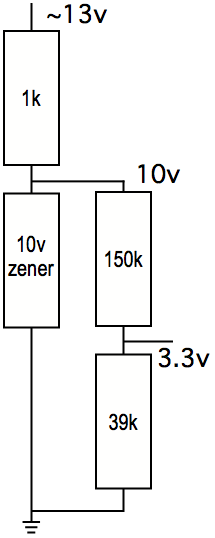
Note the original diagram shows 13V in. 24V in (from the heater 6 connector) will require NO changes.
It also shows 3.3V out. For five volt out, change the 150K and 39K in the lower right to 100K and 100K.
This is "old school" analog conversion. It will not make the signal any cleaner, but it won't make it any worse, either, in that nothing in that diagram has a limited switching speed.
-
@Danal said in Add laser for duet2 wifi:
e the original diagram shows 13V in. 24V in (from the heater 6 connector) will require NO changes.
It also shows 3.3V out. For five volt out, change the 150K and 39K in the lower right to 100K and 100K.thanks Danal for your Replay
I think this circuit is easy to build
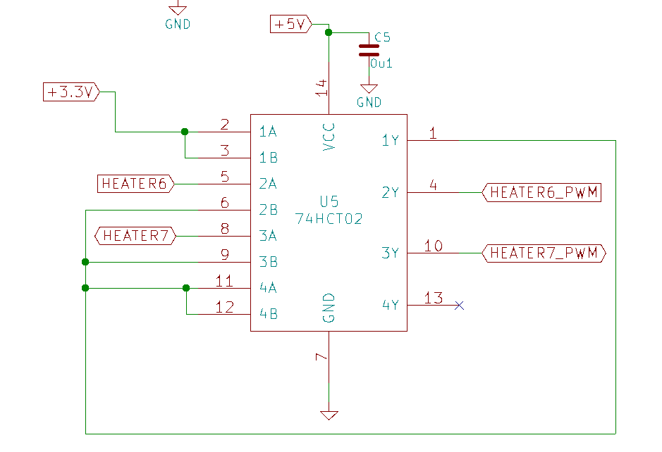
here you can see the change I make for heater 6-7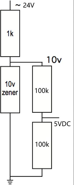
-
@yaman said in Add laser for duet2 wifi:
so after Received the part and test
it won't workI'm sorry for putting you off-course with this, I see what you mean about the DC power port being for testing; I'd assumed that was the principle power port, my apologies.
Your values and @Danal 's circuit look much more suitable. And easy to source all the parts for.
For reference in this thread: I just drew up the circuit I plan to drive my similar 15/8w diode laser module from a 3v3 controller (esp32 based) .
I will use an optocoupler, I have some at home already; the basic circuit looks like:
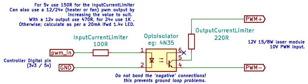
The OutputLimiter resistor is probably being over-cautions, the 4n35 can take 100mA/30v, but the laser module might provide enough residual power on the PWM lines to make it a good idea.
(Edit; I just looked at my circuit, I refer to 'nagative' values, probably a faux-pas, not a typo.]Disaster? The original Printeye is dying with RRF 3.5 (M208 depreciated).
PrintPy2024 to the rescue!
MicroPython based; with simple wiring and and no custom PCB. -
@EasyTarget circuit also looks quite good. More "standard" way in the digital world...
")
-
@yaman Yes, your modifications to the values are correct. Solder it up, wrap it in tape, and give it a try.
-
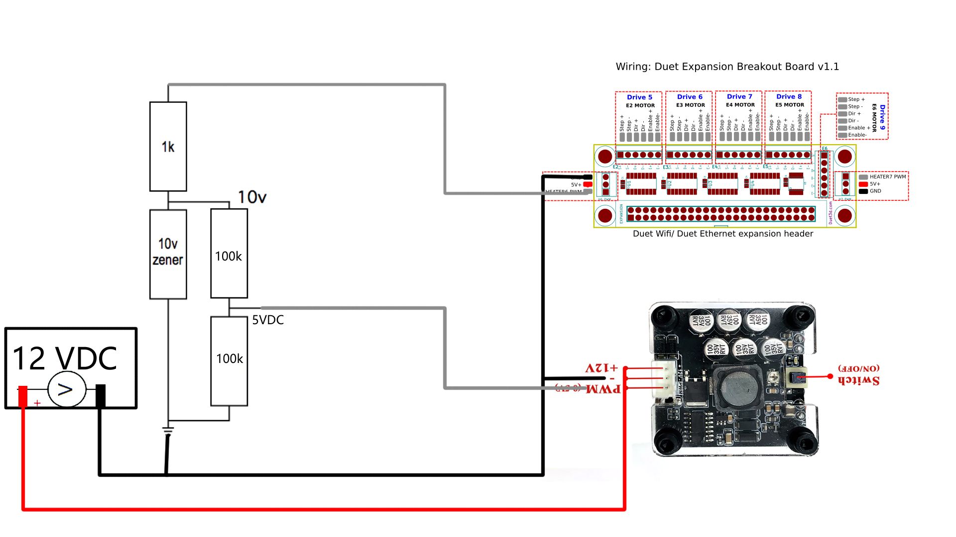
@Danal
here are the complete drawing between Laser ; header and the circuit
do I need to add anything else
-
@EasyTarget
never mind it's only 10$ -
@yaman said in Add laser for duet2 wifi:
here are the complete drawing between Laser ; header and the circuit
do I need to add anything elseLooks good to me; I was going to suggest a switch but I see you have that covered.

