Solved 3 point independent Z bed levelling issues
-
I am having issues with getting the bed to level using 3 point bed levelling and G32.
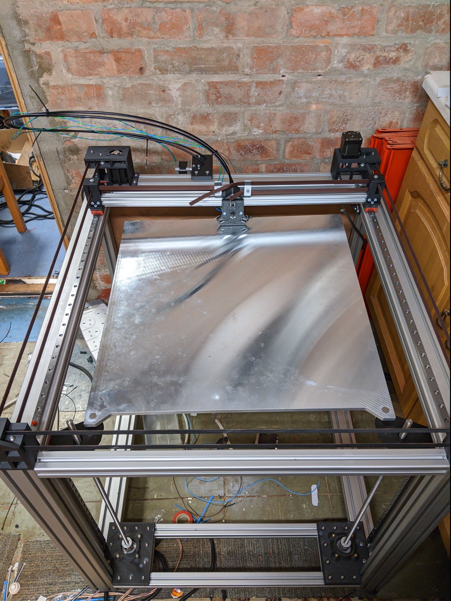
My machine is a custom built CoreXY toolchanger, inspired by the jubilee printer, with a build volume of 500x500x500.
The Z is powered by 3 independent Nema 23 stepper motors and the bed is mounted on threaded balls to allow it to rotate around the coupling and to allow for thermal expansion.I am controlling the machine with a Duet 3 running
DSF Version: 1.2.0.0
Firmware: RepRapFirmware for Duet 3 MB6HC v0.6 or 1.0 3.0RC1 (2019-12-16b8)The more I run G32, the more the bed tilts.
24/12/2019, 10:58:32	Leadscrew adjustments made: 1.709 -0.008 -1.718, points used 3, deviation before 1.360 after 0.000
24/12/2019, 10:57:32	Leadscrew adjustments made: 0.856 -0.008 -0.865, points used 3, deviation before 0.683 after 0.000
24/12/2019, 10:56:34	Leadscrew adjustments made: 0.434 -0.001 -0.434, points used 3, deviation before 0.344 after 0.000
24/12/2019, 10:55:23	Leadscrew adjustments made: 0.374 0.029 -0.059, points used 3, deviation before 0.216 after 0.000
Please find attached my config and bed files
config (3).g
bed (3).gTo get the kinematic coupling locations I homed the machine, measured the position of the head and then measured the coupling locations from the 3D model of the printer.
Here is a picture of the machine. Any ideas are welcome.
-
your config does not have an extruder defined. this can be problematic.
see
https://duet3d.dozuki.com/Wiki/Gcode#Section_M584_Set_drive_mappingVERY IMPORTANT! Assigning a drive using M584 does not remove its old assignment. Therefore, if you assign a drive that defaults to being an extruder drive, you should also assign the extruder drives explicitly as in the above example. Failure to do so may result in unexpected behaviour.
also your bed.g has G0 commands in it. they should not be there.
-
also
You must use the M671 command to define the X and Y coordinates of the leadscrews. The M671 command must come after the M584 command and must specify the same number of X and Y coordinates as the number of motors assigned to the Z axis in the M584 command; and these coordinates must be in the same order as the driver numbers of the associated motors in the M584 command. The M671 command must also come after any M667 or M669 command. -
I have this in my config
; Leadscrew locations (really, kinematic coupling locations) extracted from CAD model assuming back right build plate corner is (0, 0)
M671 X484.5:-6:244.5 Y548.5:548.5:17 S20 		; Front Left: (484.5, 548.5) | Front Right: (-6, 548) | Back: (244.5, 17)
And I know I don't have an extruder defined as I don't have enough drivers yet. I'm waiting on an expansion board to come.
Owns various duet boards and is the main wiki maintainer for the Teamgloomy LPC/STM32 port of RRF. Assume I'm running whatever the latest beta/stable build is
-
@jay_s_uk What's your M584 command?
Ian
-
-
@jay_s_uk said in 3 point independent Z bed levelling issues:
And I know I don't have an extruder defined as I don't have enough drivers yet. I'm waiting on an expansion board to come.
the problem with that is that the initial configuration still applies so your will have z motors which are both z motors and extruders at the same time. this will case problems with steps and current etc.
-
@Veti
But I don't have any driver left so how do I define an extruder? -
hmm try using 0.2 for both u and e
M569 P0.3 S0 ; Drive 3 direction | Front Left Z
M569 P0.4 S0 ; Drive 4 direction | Front Right Z
M569 P0.5 S1 ; Drive 5 direction | Back Zalso that seems straing that one z motor goes in the opposite direction
-
The bed moves in the correct direction to move up and down, but I'll check the wiring to see if one of the coils has been reversed.
Could it be that it's assumed by G32 that all of the motors are moving in the same direction so it ignores the one moving in the other direction?
-
@jay_s_uk said in 3 point independent Z bed levelling issues:
24/12/2019, 10:58:32 Leadscrew adjustments made: 1.709 -0.008 -1.718, points used 3, deviation before 1.360 after 0.000
24/12/2019, 10:57:32 Leadscrew adjustments made: 0.856 -0.008 -0.865, points used 3, deviation before 0.683 after 0.000
24/12/2019, 10:56:34 Leadscrew adjustments made: 0.434 -0.001 -0.434, points used 3, deviation before 0.344 after 0.000
24/12/2019, 10:55:23 Leadscrew adjustments made: 0.374 0.029 -0.059, points used 3, deviation before 0.216 after 0.000look at those values. this indicate with every measurements that it gets worse not better.
this highly suggests that you have not observed the correct order of your motors, as stated above. -
I've checked each driver to make sure it is controlling the correct motor and I'm 100% sure the order is as stated above.
3 is front left
4 is front right
5 is back middleThis falls inline with the order in M584, the order in M671 and the order of the probe points in the bed file.
-
from the output my guess would be that 3 and 5 needs to be swapped.
i find your 0,0 position highly confusing as everyone is using front left as 0,0. -
Well it just gets stranger and stranger.
I swapped a coil in driver 5 (which was the one that was set the opposite way to the others). This made the stepper go the opposite way.
So I changed the config to suit, reloaded it and then drivers 3 and 5 were going the right way and 4 wasn't.
I then swapped a coil on driver 4 and then when I commanded the bed to go down it went up.
Changing the config to S1 for all drivers resulted in the bed going down when it was supposed to.
I ran G32 and it's still getting worse but this time the bed is going down at the back.
Very strange indeed.I think I may need to revisit the wiring. But what I don't understand is why changing one motor effected the others. They're all wired independently with each pair of wires twisted together.
-
And 0,0 is at the back right due to tools being positioned at the front, preventing homing
Owns various duet boards and is the main wiki maintainer for the Teamgloomy LPC/STM32 port of RRF. Assume I'm running whatever the latest beta/stable build is
-
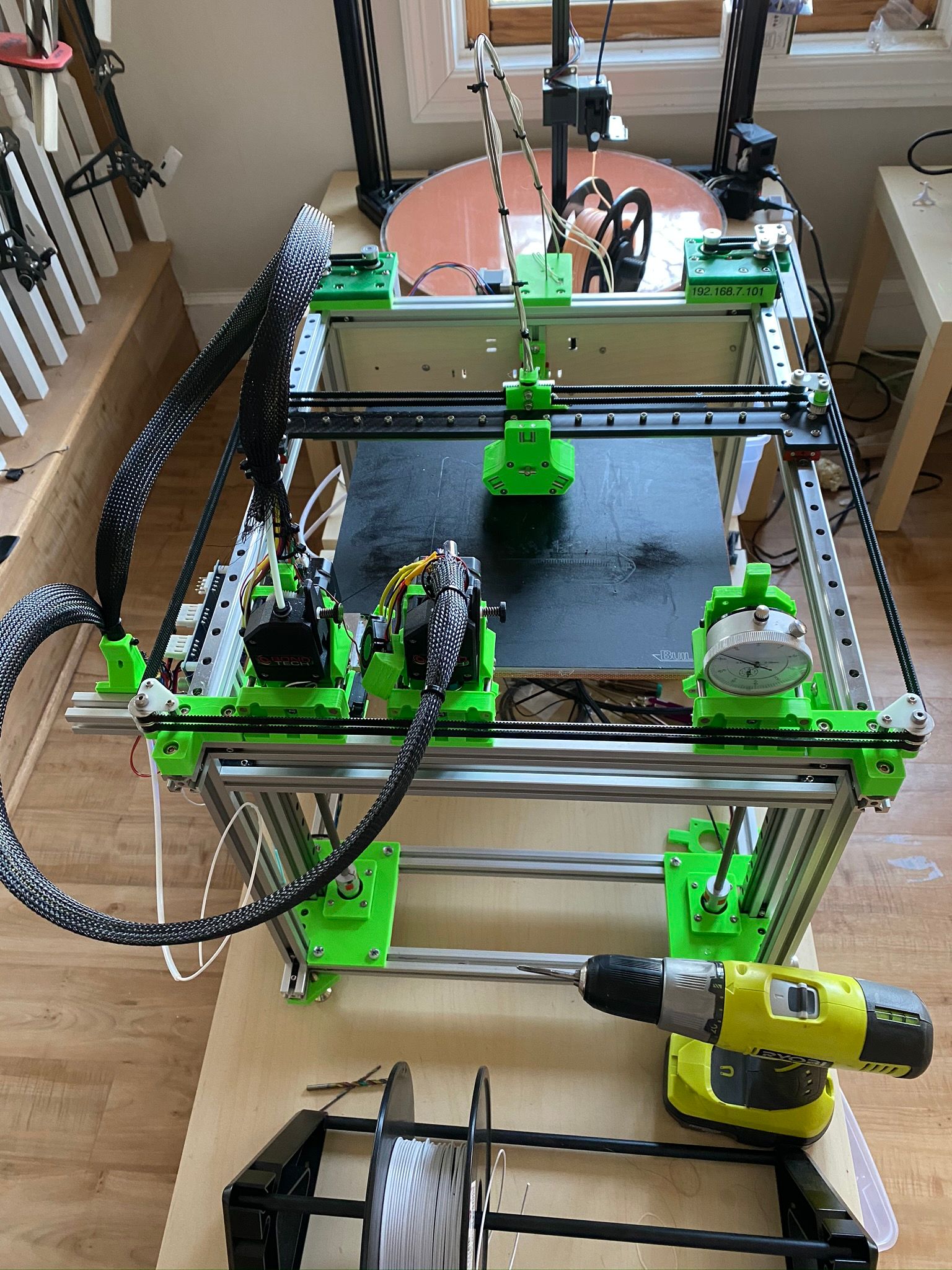
I have a jubilee built very close to plan. Attached is a working config.g. Specifically, all bed travel, and all bed tram/level works properly. I did not rewire any motors.
Please note that the "front left" coordinates specified in bed.g are a little odd because I'm conducting some experiments at the moment (with tool-to-tool alignment probing) and there is a chunk of Alu bolted to the left front of the bed. This must be avoided for the moment. Eventually, it will be mounted in a better place... I'm just experimenting.
Anyway, files attached.
And, if your bed dimensions (and therefore kinematic couplings) exactly match the Jubilee original files on Github, here is the correct: M671 command:
; Leadscrew locations (really, kinematic coupling locations) extracted from CAD model assuming back right build plate corner is (0, 0)
M671 X300:5:152.5 Y316:316:-14 S10 ; Front Left: (300, 316) | Front Right: (5, 316) | Back: (-14, 152.5)
And, because the probe cant really reach EXACTLY over those couplings, expect to run G32 a couple of times, and let it "converge" to .001 correction or better.
Oh, and Hi Jay!!
-
@Veti said in 3 point independent Z bed levelling issues:
i find your 0,0 position highly confusing as everyone is using front left as 0,0.
It may seem odd, but as Jay said, it works out better for a Toolchanger.
If it still throws your mind for a loop, walk around and look the printer from "behind". Viola! Origin is now "normal"-ish, nearest your left hand.
Delta / Kossel printer fanatic
-
@jay_s_uk said in 3 point independent Z bed levelling issues:
And 0,0 is at the back right due to tools being positioned at the front, preventing homing
I don't understand why you think that is so.
Could you explain?
Thanks.
Frederick
-
The XY homing switches can't be behind the tools. The homing switches are in the "back right" when looking at the printer from the POV in the photo. That is, the tools are at the "front".
And, again, this is all quite arbitrary regarding what we declare to be the "front" of the printer. Stand where my big delta is and look, with the thought that you are now looking at the "front" of the printer. The side without tools. Now the origin is front/left. The printer and the numbers in a piece of GCode certainly don't care what we call "front" or "back".
Also note that this is a pure rotation, so there is no mirroring, or anything like that. Just arbitrary "front" v "back"
-
@jay_s_uk said in 3 point independent Z bed levelling issues:
And 0,0 is at the back right due to tools being positioned at the front, preventing homing
the 0,0 position has no effect on homing.
if you can home now, you can home when the bed position is at 0,0 at the bottom left.
you just home to max instead of min.