Stepper motors not turning
-
Hi, I am not very good with electronics, but I made this coreXY printer and I am wiring the Duet2 WiFi on it. Just noticed that there is also a new firmware, so I did that today as well.
My trouble is I can't get the XY axes stepper motors to turn. They vibrate, but won't turn and they start to make a whining noise. If you try to rotate them - they resist, but then give in and go out of control - either vibrating or spinning without end. Which is the reason why I need help, because I don't know what is causing this.
I have wired 4 of the same brand motors on top to move the Z axis and that goes up and down no problem, but the XY motors are making really unhappy noises.
Things I tried - 1. flipping the cable colors on the Duet side (this is in case the motors are wired incorrectly). To my surprise that did nothing, I really thought that was causing the motors not to spin.
Right now the color scheme is Red/Blue/Green/Black on the Duet side > Red/Black/Blue/Green (I still could be wrong on running them like that, I don't know anymore)
2.Changing the config file and eventually updating the firmware and web control to the final version.
No noticeable difference in anything, except now the commands I use to check the rotation of the motors are different (S changed to H)
Things I haven't tried - changing voltage to the stepper motors. Right now they are all set to Motor current 900mA. They have a current rating at 2.5A/Phase, but in the Configurator the allowed range is 300 to 2400, default 800mA, so I thought that might be OK since the other motors run fine.I'm sure it is a trivial problem that I just don't know about. I tried all kinds of helps and troubleshoots and forums, but I couldn't find something that helps me, so I decided to ask here. Hope someone knows exactly what I'm doing wrong.
-
Do you have details of the stepper motors?
If you have a multimeter, you can check which colours are from each coil? If you measure between the red wire and the blue wire, you should have no resistance.
If red and blue are one coil, and green and black are the other coil, then your wiring order seems correct and the next thing to look at is the crimping of the terminals. -
@id104335409 Can you post your config.g file as well please.
-
@id104335409 Try swapping motors on the motor driver pins, to see if the problem follows the motor, or stays with the driver. I'd think most likely is that there is one phase of each motor that is not connected, ie one of the four wires is not making a connection. This could be caused by a wire break, or a poorly crimped crimp. If you have a multimeter you can disconnect the motor and check the continuity of each pair of wires. See here for other ways to test for the motor phases: https://duet3d.dozuki.com/Wiki/Choosing_and_connecting_stepper_motors#Section_Identifying_the_stepper_motor_phases
This may also help: https://duet3d.dozuki.com/Wiki/Choosing_and_connecting_stepper_motors#Section_Checking_connected_stepper_motorsRemember to turn off power before connecting or disconnecting motors from the pins on the Duet. You can damage the stepper driver if you don't!
Ian
-
-Manufacturer: LDO
-Model: LDO-42STH47
-Holding Torque: 5.5 kg/cm - 76oz-in
-Shaft: 5mm
-Voltage rating: 3.1V
-Stepping angle:1.8 degrees
-Current rating: 2.5A/Phase
-Connector type: JST PH-6
.................................................................................................................................; Configuration file for Duet WiFi (firmware version 3)
; executed by the firmware on start-up
;
; generated by RepRapFirmware Configuration Tool v2.1.8 on Thu Jan 30 2020 16:44:56 GMT+0200 (Eastern European Standard Time); General preferences
G90 ; send absolute coordinates...
M83 ; ...but relative extruder moves
M550 P"QB" ; set printer nameM667 S1 ; select CoreXY mode
; Network
M552 S1 ; enable network
M586 P0 S1 ; enable HTTP
M586 P1 S0 ; disable FTP
M586 P2 S0 ; disable Telnet; Drives
M569 P0 S1 ; physical drive 0 goes forwards
M569 P1 S1 ; physical drive 1 goes forwards
M569 P2 S1 ; physical drive 2 goes forwards
M569 P3 S1 ; physical drive 3 goes forwards
M584 X0 Y1 Z2 E3 ; set drive mapping
M350 X16 Y16 Z16 E16 I1 ; configure microstepping with interpolation
M92 X80.00 Y80.00 Z1600.00 E420.00 ; set steps per mm
M566 X900.00 Y900.00 Z12.00 E120.00 ; set maximum instantaneous speed changes (mm/min)
M203 X18000.00 Y18000.00 Z180.00 E1200.00 ; set maximum speeds (mm/min)
M201 X3000.00 Y3000.00 Z20.00 E250.00 ; set accelerations (mm/s^2)
M906 X900 Y900 Z900 E900 I30 ; set motor currents (mA) and motor idle factor in per cent
M84 S30 ; Set idle timeout; Axis Limits
M208 X0 Y0 Z0 S1 ; set axis minima
M208 X500 Y500 Z500 S0 ; set axis maxima; Endstops
M574 X1 S1 P"xstop" ; configure active-high endstop for low end on X via pin xstop
M574 Y1 S1 P"ystop" ; configure active-high endstop for low end on Y via pin ystop
M574 Z1 S1 P"zstop" ; configure active-high endstop for low end on Z via pin zstop; Z-Probe
M558 P0 H5 F120 T6000 ; disable Z probe but set dive height, probe speed and travel speed
M557 X15:215 Y15:195 S20 ; define mesh grid; Heaters
M308 S0 P"bedtemp" Y"thermistor" T100000 B4138 ; configure sensor 0 as thermistor on pin bedtemp
M950 H0 C"bedheat" T0 ; create bed heater output on bedheat and map it to sensor 0
M143 H0 S120 ; set temperature limit for heater 0 to 120C
M307 H0 B0 S1.00 ; disable bang-bang mode for the bed heater and set PWM limit
M140 H0 ; map heated bed to heater 0
M308 S1 P"e0temp" Y"thermistor" T100000 B4138 ; configure sensor 1 as thermistor on pin e0temp
M950 H1 C"e0heat" T1 ; create nozzle heater output on e0heat and map it to sensor 1
M143 H1 S280 ; set temperature limit for heater 1 to 280C
M307 H1 B0 S1.00 ; disable bang-bang mode for heater and set PWM limit; Fans
M950 F0 C"fan0" Q500 ; create fan 0 on pin fan0 and set its frequency
M106 P0 S0 H-1 ; set fan 0 value. Thermostatic control is turned off
M950 F1 C"fan1" Q500 ; create fan 1 on pin fan1 and set its frequency
M106 P1 S1 H1 T45 ; set fan 1 value. Thermostatic control is turned on; Tools
M563 P0 D0 H1 F0 ; define tool 0
G10 P0 X0 Y0 Z0 ; set tool 0 axis offsets
G10 P0 R0 S0 ; set initial tool 0 active and standby temperatures to 0C; Custom settings are not defined
; Miscellaneous
M911 S10 R11 P"M913 X0 Y0 G91 M83 G1 Z3 E-5 F1000" ; set voltage thresholds and actions to run on power loss....................................................................................................................................
I checked the motors with the multimeter and they seem to be fine. Also traced the wires, they are also fine. But the pins inside the connectors do wiggle. I do have one more cable - I could swap it with the ones I tested and try the motor again...
I am really annoyed how fragile the cables and pins and the Duet PCB is, but the connectors are HARD AS NAILS, so I have to really push/pull, but at the same time I have to be gentle. -
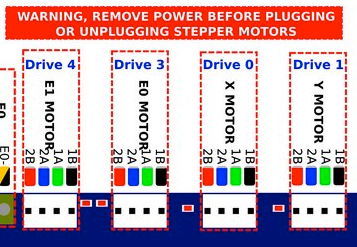
@id104335409 I think you have the motors wired incorrectly; looking at the data sheet http://ldomotors.com/uploads/product_attachment/path/6/LDO-42STH_Info_Sheet.pdf it shows the pairs of wires for each phase are black/green and red/blue. So at the Duet end they should be wired in this order, as the motor driver output pin order is 2B 2A 1A 1B, where the 2s are the pair of wires for one phase, and 1s are the other. The order of each pair doesn't matter, but getting the pairs together does. You can follow the colours on the wiring diagram https://d17kynu4zpq5hy.cloudfront.net/igi/duet3d/vqBUAZPsxMC5tRgt.huge
If this doesn't work, the link I posted earlier shows how to identify the wires of each phase, even without a multimeter; did you try this?
You will also want to set the current between 50% and 85% of its rated current, so with a 2.5A motor, set the currents to between 1.25 and 2.1A. I'd say around 2A would be fine. With 900mA you're at risk of under-powering the motor, though I'd be surprised if it stalls, unless you've already hooked it up to the axes. So change the M906 line to:
M906 X2000 Y2000 Z900 E900 I30 ; set motor currents (mA) and motor idle factor in per cent
The motors on Z and E are different?See this page for our general recommendations and guidance about stepper motors (parts of which I linked earlier): https://duet3d.dozuki.com/Wiki/Choosing_and_connecting_stepper_motors
Note that 0.9º motors for X and Y usually provide the best results on CoreXY machines, rather than 1.8º.Ian
-
Thank droftarts, the wires to the motors were wired incorrectly - the colors were matching those of the Duet in order for them to work. I am definitely going to up the current to them as well as you recommended.
Yes, the Extruder motor is different. I will apply what I learned to it as well. Separate settings.
No, I didn't know that 0.9º motors for X and Y provide better results on CoreXY machines.So, motors not running properly - solution: switch cables on motors if possible.
Thank you all.
If I have more questions should I just post here or make a separate post? -
@id104335409 said in Stepper motors not turning:
If I have more questions should I just post here or make a separate post?
Glad you got it working. I’d tend to say start a new thread for each individual issue, otherwise threads can get very long and convoluted. Make sure you state Machine setup, firmware version and post current config each time, this goes a long way to getting problems resolved quickly, as people have the context for the problem. Or see https://forum.duet3d.com/topic/5909/guide-for-posting-requests-for-help
Ian