Independted dual Z & Manual bed leveling assistant question
-
Hello everyone, I would not be surprised if the same question has been asked before, but I did not find an answer searching the forum so here it is:
Some background:
I followed this guide to set up my Dual independent Z:
https://duet3d.dozuki.com/Wiki/Bed_levelling_using_multiple_independent_Z_motorsBefore, I was quite fond of the Manual bed leveling assistant, and I used the config as explained here:
https://duet3d.dozuki.com/Wiki/Using_the_manual_bed_levelling_assistantNow the problem: when I was using the manual one, I had the 3 adjustment screws with the positions set via the M671 and I was probing as close as possible at each one of them. Then, I had the very nice console output on how much I should adjust each screw.
Converting to dual Z I had to change the M671 to define the position of each leadscrew. While that is perfect for the X axis (2 opposite leadscrews along that axis), and height difference is corrected by the motor automatically, this does not include the Y axis compensation.
As I understand, I can use the dual independent Z for X axis, and maybe the bed mesh compensation to account for the Y, but my question is:
Is it possible to define both the positions of the leadscrews and the adjustment screws differently, so i can get this nice console output while still using the dual Z.
I think of it like a sequence of probing close to the leadscrews -> motors adjusting ->probing close to adjustement screws->console output to adjust the screws. At the moment whenever I need to level the bed I am doing it by manually moving the head close the adjustment screws and checking the nozzle offset with a 0.1 feeler gauge.
Am i missing something?
P.S. I know from the theory that I need 3 points to define a plane, therefore I can have one point as reference and adjust the other 2 with the motors. For my system to work like this though, it will require mechanical changes that I can not implement at the moment.
-
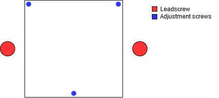
It will be easier to answer your question if you post a diagram showing the positions of the drive screws and the leveling screws.
-
As you have only 2 Z motors so you can't auto-adjust the Y bed tilt, I suggest you set up two macro files. Or alternatively, you can put all the commands in bed.g so that you run them one after the other.
In the following I will assume that you have levelling screws at the rear left and right and front centre.
First use standard leadscrew bed levelling. Run M671 to define the leadscrew positions, and probe 2 points at back left and back right.
Then run M671 again but this time define the adjusting screw positions, starting with back left or back right and ending with front centre. Then probe 3 points close to the adjusting screws. As M671 defines 3 points but you have only 2 motors, it will suggest manual corrections. The first will be zero, the second should be very small because you have already levelled the bed in X (if it isn't small then you may wish to run bed levelling again). The third will be the correction for the front right screw.
You've given me an idea, which is to support auto levelling with 3 sets of coordinates and 2 motors, such that the firmware assumes that the 3rd coordinate is a manual screw and suggests a correction for it.
-
@mrehorstdmd Yes, of course:

-
@dc42 Thanks for the detailed explanation! I think I understand what I have to do, it should be easy. I did not thought of providing two different M671 command chains in sequence.
You've given me an idea, which is to support auto levelling with 3 sets of coordinates and 2 motors, such that the firmware assumes that the 3rd coordinate is a manual screw and suggests a correction for it.
That was basically how I initially pictured it will work, would be great!
-
@Dkos yes, it’s possible, I run my machine with both X axis levelling and manual three point levelling. I have macros set up to do exactly this. I’ll post them when I get back home.
Ian
-
@Dkos Note that you need to set either the bed or the X gantry square to the Z axis first, so you have something square to start with and measure from.
My method:
- Manually square the X gantry to the frame/Z rods
- Run the 3-point manual bed macro to square the bed to the X gantry
- Use G32 bed mesh (bed.g) to tram the Y axis, which usually means putting a shim under either the back or front foot on the left, to level the Y rods
This usually produces a nice flat bed, and I don't need to use mesh compensation. Once the manual levelling has been done, it rarely moves, so on each subsequent power cycle, I just level X gantry to bed and occasionally do a bed mesh to check. I use an IR probe for probing. X0 Y0 is in the centre of the bed. Board is Duet WiFi 1.0 or 1.0, firmware is RRF 3.01-RC2 (2020-02-18b1)
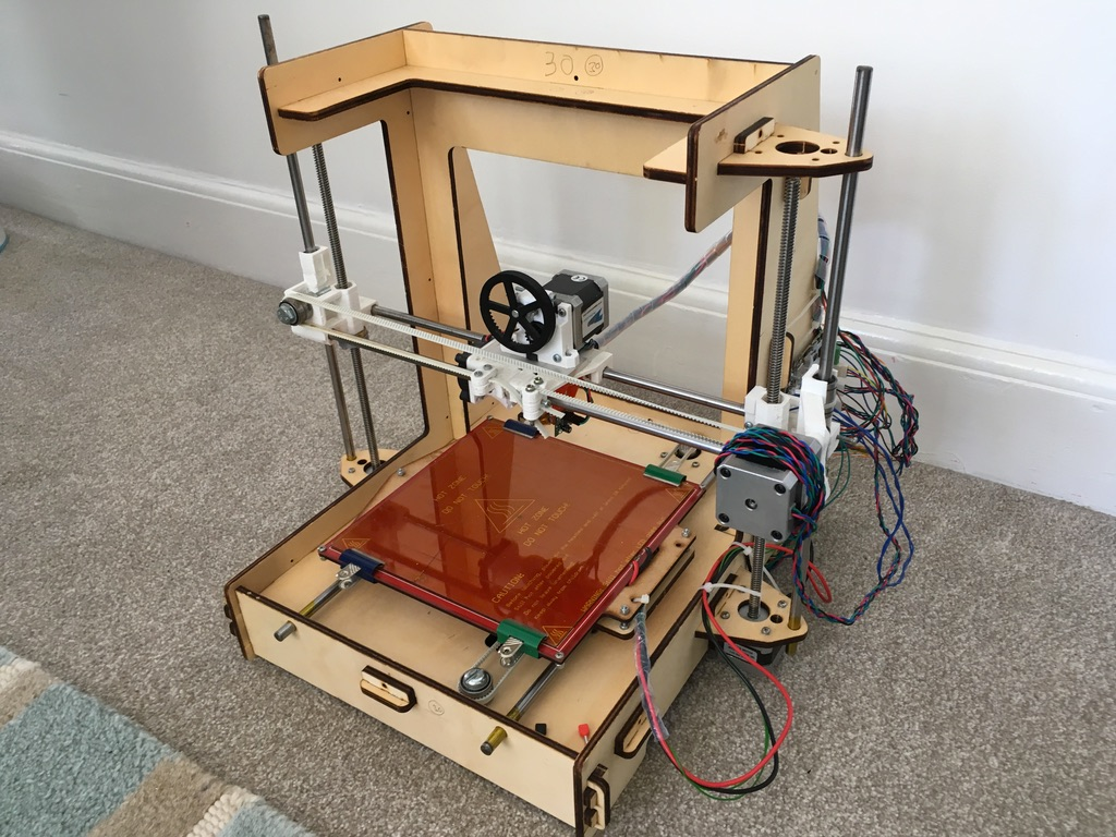
This is my machine, for reference. Bed has two manual adjusters on right, one on left:

Relevant bits of config.g:
; Dual Z
M584 X0 Y1 Z2:3 E4                                 ; Set drive mapping

; Axis Limits
M208 X-106 Y-110 Z0 S1                             ; set axis minima
M208 X114 Y118 Z180 S0                             ; set axis maxima

; Z-Probe
M558 P1 C"zprobe.in+zprobe.mod" H5 F120 T6000      ; set Z probe type to unmodulated and the dive height + speeds
G31 P500 X20 Y0 Z1.25                              ; set Z probe trigger value, offset and trigger height
M557 X-85:85 Y-85:85 P5                            ; define mesh grid
With the macros, the main thing is you define the leadscrew positions for the three adjuster screws in the manual-bed macro, and the leadscrew postition for the Z leadscrews in the X-levelling macro.
0:/macros/manual-bed.g
G29 S2                            ; disable compensation
M671 X120:120:-118 Y46:-46:0 P0.5 ; adjusting screws at rear right (120,46), front right (120,-46) and middle left (-118,0), thread pitch M3 0.5mm
G30 P0 X95 Y46 Z-99999            ; probe near an adjusting screw
G30 P1 X95 Y-46 Z-99999           ; probe near an adjusting screw
G30 P2 X-85 Y0 Z-99999 S3         ; probe near an adjusting screw and report adjustments needed
G1 X0 Y0 F6000
0:/macros/X-levelling
G29 S2                            ; disable compensation
M671 X-181.5:181.5 Y0:0 P0.5     ; leadscrews at left (-181.5,0) and right (181.5,0)
G30 P0 X-85 Y0 Z-99999            ; probe near an adjusting screw
G30 P1 X85 Y0 Z-99999 S2         ; probe near an adjusting screw and report adjustments needed
G1 X0 Y0 F6000
0:/sys/bed.g
; bed.g
; called to perform automatic bed compensation via G32
;
; generated by RepRapFirmware Configuration Tool v2.1.6 on Tue Jan 14 2020 12:35:54 GMT+0000 (Greenwich Mean Time)
M561 ; clear any bed transform
G29  ; probe the bed and enable compensation
Hope that helps. Feel free to ask any questions!
Ian
-
@droftarts Thanks for sharing! It is nice to see an already working implementation. I will work on it (among some other things) over the weekend and will post back the results
