12V on the 5V rail
-
@Haggan90 Usually terminal. See https://duet3d.dozuki.com/Wiki/How_to_destroy_your_Duet_2
Ian
-
 image url)
If I connected 12VDC there (beautiful red arrow), am I screwed then?

-
@Haggan90 said in 12V on the 5V rail:
How screwed am I if I manage to connect 12VDC on the 5VDC rail?
Unfortunately, for every 3D printer controller board on the market except Duet 3, that will usually cause multiple components to fail. As it was 12V not 24V, there is a chance that one of the components on the 3.3V rail (most likely SD card or WiFi module) will have failed in such as way as to protect the rest. To test that you would need to remove the 3.3V regulator chip and the 74HCT02 mosfet driver chip, apply an external 3.3 supply to the 3.3V rail (or you could replace the 3.3V regulator chip and apply USB power), and see what gets hot. If the processor doesn't get hot, it's worth trying to connect to it over USB; and if that doesn't work, use the Erase jumper and see if you can get he Bossa port to appear (because I've heard of an over-voltage erasing the firmware but the processor still working afterwards).
Duet 3 has been designed to survive that type of accident, although other devices powered from the 5V rail (e.g. RPi or PanelDue) would have been damaged.
-
@dc42 do you think mt duex2 got damage as well?
-
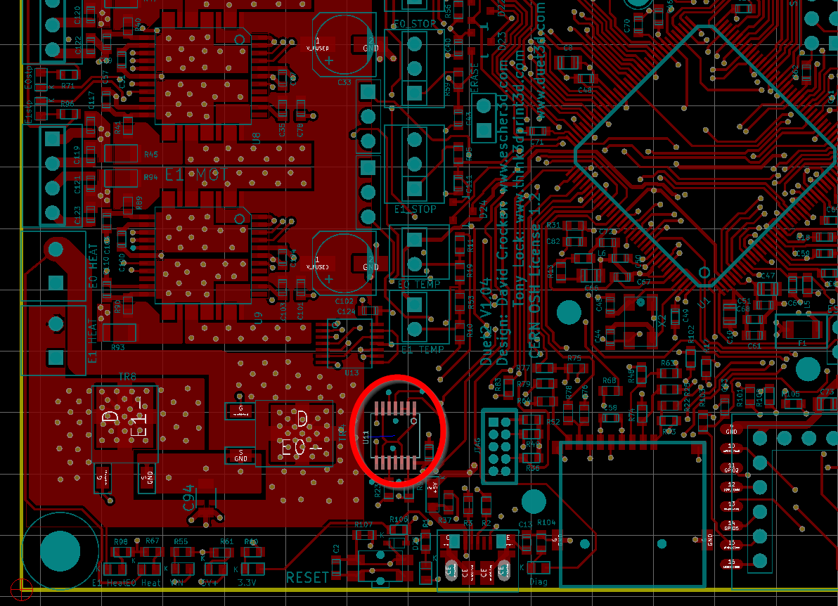
@dc42 I can't find the 74HCT02 chip.
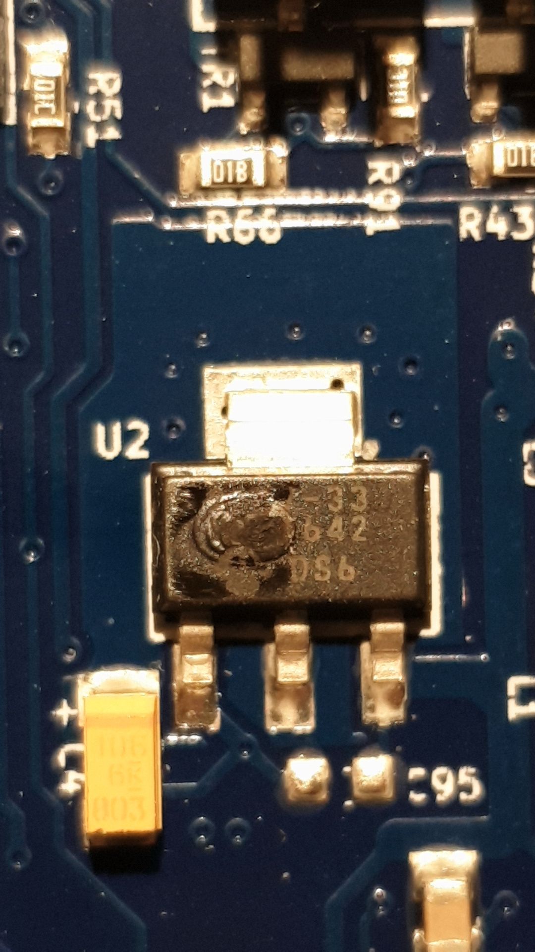
The only component that seems off is this one.
-
-
@bearer Yeah, that's what I tought.. Could it be fixed if I just replaced U2?

What does U2 do? -
@Haggan90 said in 12V on the 5V rail:
Could it be fixed if I just replaced U2?
Theoretically. It provides 3.3v to the system. U11 / 74HCT02 drives the heater mosfets. But there could be more damage as well. I'd remove U2 and apply an external, preferably current limited supply to test.
-
@bearer Ok!
I've removed U2, where can I connect 3.3V and what should I set the current limit to?
Btw, I tried the SD card and it seems to work fine. -
A current limit of 200mA should be enough if nothing else is damaged, until you turn the WiFi module on. With WiFi on you may need 600mA.
-
@Haggan90 said in 12V on the 5V rail:
where can I connect 3.3V and what should I set the current limit to?
i've found that making a cable to connect to CONN_SD gives me convenient access to gnd, 3v3 and 5v connections. You can use single du-pont style wires as well. In general you can use any 3.3v pin shown on the wiring diagram. as dc42 said, 200mA is a good starting point; if it goes into current limiting mode try 300mA but if it takes more than a second or two to charge up capacitors and start up then start looking for what gets warm.
-
@Haggan90, you can find the duet wifi schematics in the link below. It may help you understand what's is going on.
-
You can feed the 3.3V into any endstop connector.
-
@dc42 I connected 3.3V and nothing got hot.
When I connected USB I got 4.4V in the 3.3V rail... -
@Haggan90 said in 12V on the 5V rail:
When I connected USB I got 4.4V in the 3.3V rail...
after removing the 3.3v volt regulator? strange, please post a picture of the board?
-
@bearer I connected 3.3V to where the regulater output was.

-
@Haggan90 said in 12V on the 5V rail:
@dc42 I connected 3.3V and nothing got hot.
When I connected USB I got 4.4V in the 3.3V rail...Remove the other blown chip too.
-
@dc42 You mean the U11 / 74HCT02?
-
-
@dc42 aha ok! I have to do that at work where we have a hot air solder gun
