12V on the 5V rail
-
@dc42 hi!
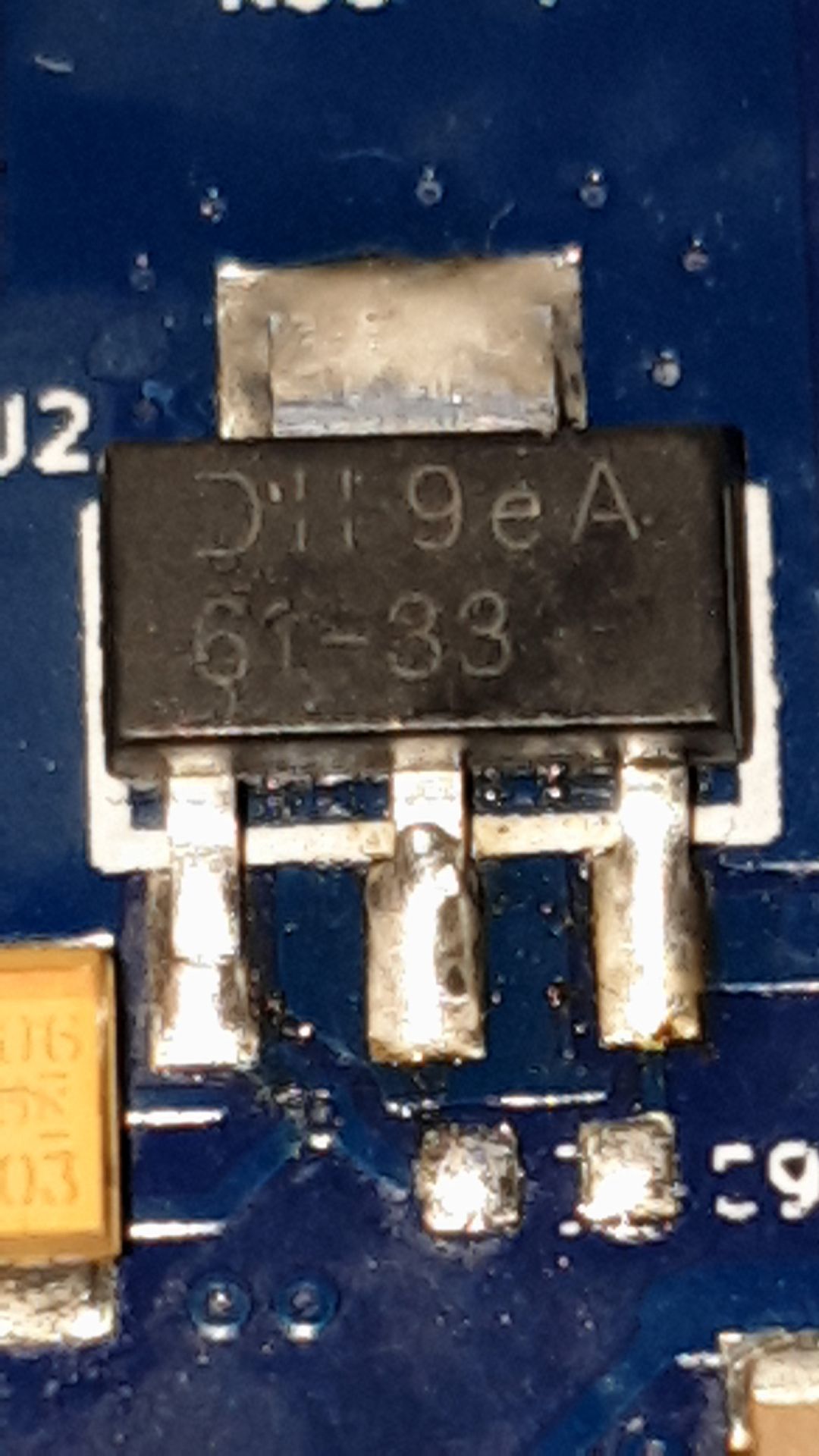
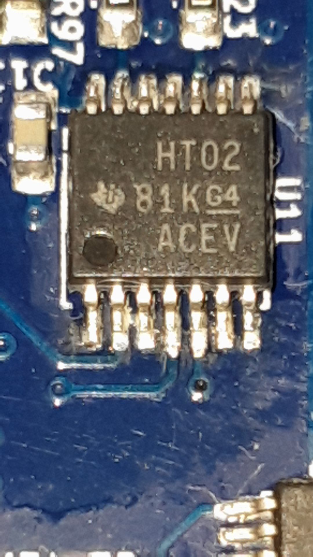
As far as I can nothing else get's hit then the U2. Here are the new components.


-
What part number did you use for the 3.3V regulator, and what hardware revision Duet board is it? I think you may have used the wrong regulator.
-
@dc42 Hi,
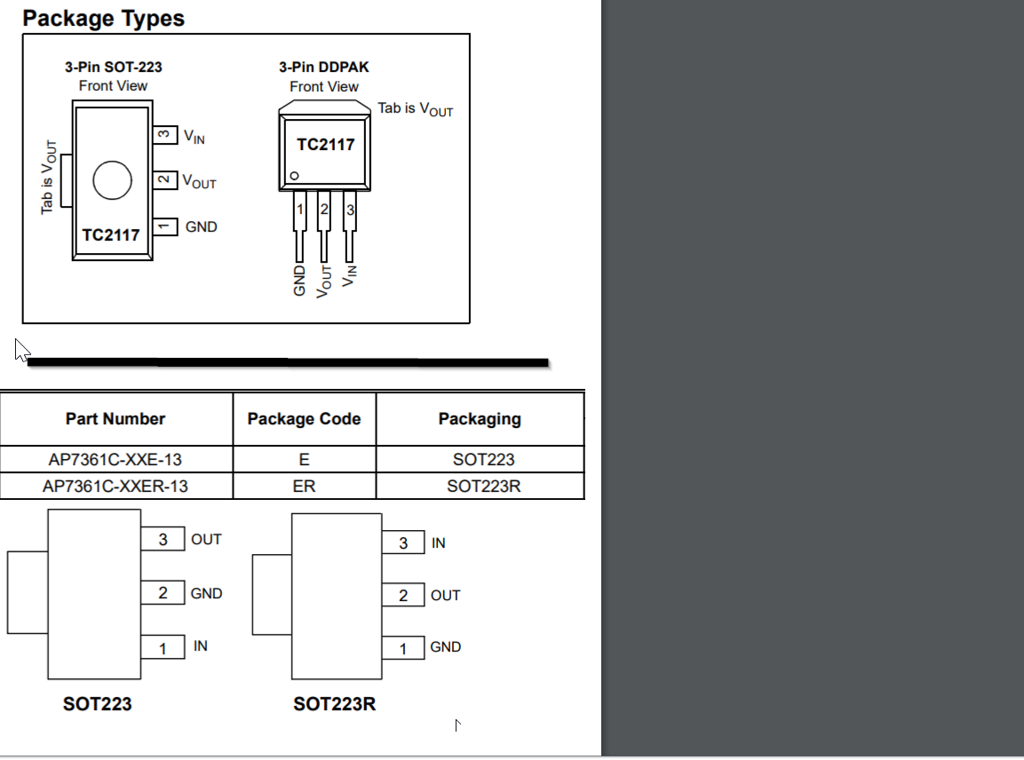
As voltage regulator I used a: AP7361C-33E-13
And as the U11 mosfet driver I used a : SN74HCT02PWR -
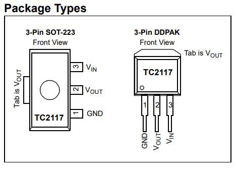
looks like the board is a revision 1.03 board that uses a TC2117 which is not compatible with AP7361C-33E-13 but
shouldcould be compatible with AP7361C-33ER-13
-
@bearer Aw crap haha

Might I have destroyed the PCB even more now? -
@Haggan90 not sure; i would guess u2 took the blunt of the force this time as well.
you'll just have to remove it and see if the board still works with external 3.3v I guess (or wait for the correct part)
But do double check it is a rev 1.03 board
-
@bearer Ok!
Yeah, It is a V1.03 board.
Is it possible that the Wifi Module and the SD card reader is OK or do I have to change one/both of them as well? -
@Haggan90 as I said I'm not sure, head isn't quite on the right way but I'm guessing you essentially fed -5v into the 3.3v output of the regulator which it didn't like.
odds are if nothing else got warm the damage is contained, but as i said, remove the wrong regulator and test it with an external supply and you'll have the answer.
-
@bearer said in 12V on the 5V rail:
but should be compatible with AP7361C-33ER-13
@Haggan90 just clicked in my head the AP7361C doesn't specify if the tab is connected to v-out or gnd or anything at all; so I can't say for sure if it works.
TC2117-3.3VDBTR is the full partno from the 1.03 schematic.
-
@bearer said in 12V on the 5V rail:
TC2117-3.3VDBTR

IS this the correct one?
https://www.digikey.se/product-detail/sv/microchip-technology/TC2117-3-3VDBTR/TC2117-3-3VDBCT-ND/7065613 -
has the same manufacturer part number as on the schematic at least, so thats about as sure as I can get.
"Tillverkarens artikelnummer TC2117-3.3VDBTR"
(the key to decoding the part numbers are usually towards the end of the datasheets, helps decode the various letters and numbers)
-
@bearer Hi!
I have now changed the U2 and I can connect to the board via USB

It seems like maybe the WiFi module is broken, but is there any way I can check that over YAT? -
just follow the getting started guide to set up wifi again, if it responds to M552 and connects you're good.
-
@bearer ok!
The blue LED does not light up on start, is that a bad thing? -
@Haggan90
Ok, it seems like I can't get the Wifi module into idle mode.
Also, I do belive it get's a bit warm, not hot but warm.M115 FIRMWARE_NAME: RepRapFirmware for Duet 2 WiFi/Ethernet FIRMWARE_VERSION: 2.05.1 ELECTRONICS: Duet WiFi 1.02 or later FIRMWARE_DATE: 2020-02-09b1<LF>ok<LF> M552 S-1 WiFi module stopped<LF>ok<LF> M552 WiFi module is disabled<LF>ok<LF> M552 S0 ok<LF> M552 WiFi module is being started<LF>ok<LF> M552 S0 ok<LF> M552 S0 ok<LF> M552 WiFi module is being started<LF>ok<LF> M587 M587: Failed to retrieve network list<LF>ok<LF> -
@Haggan90 try deleting all saved wifi networks with
M588 S"*"(That is, using an asterix for the network name), then re-adding it with M587. For example,M587 S"networkname" P"password". -
@Phaedrux Hi, I get this:
M588 S"*" M588: Failed to reset the WiFi module to factory settings<LF>ok<LF> -
@Phaedrux The SD-Card seems to be fine.
Do I need a hot air desoldering station to change the Wifi Module? And, what would I need to do after I've changed it?
This is what I get when sending M21.M21 SDHC card mounted in slot 0, capacity 3.98Gb<LF>ok<LF> -
@Haggan90 said in 12V on the 5V rail:
Do I need a hot air desoldering station to change the Wifi Module?
A good preheating and some quickchip or similar 138C-ish melting point solder might to the trick; but most likely "yes".
edit: oh, and after all you need to do is run M997 S1, presuming the wifi firmware file is in the /sys folder on the SD card.
-
@bearer Thank you! I will see what I come up with to desolder it

Is there any special version of the ESP-12S Wifi Module I need?