CR10v2 - Duet 3 Connections - Part 2
-
So I think I have all of the connections from the Duet 3 to my CR10V2. When I power up the printer, the BLTouch does its self test. That is about the only thing that is working. I am including my updated config.g file at the end of the post.
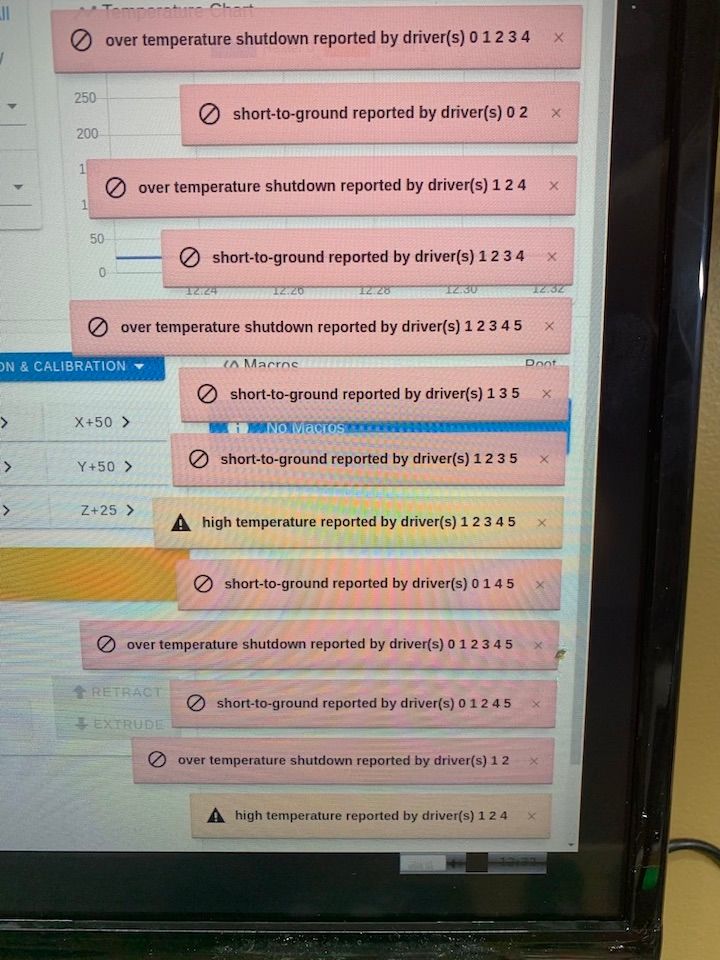
Here is what is happening. I turned on the machine and within about 5 minutes, I looked up and saw this:
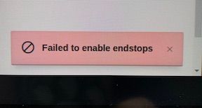
I restarted and tried to Home the Y axis and this popped up:
Obviously, there are some wiring problems. Here is how/where I have my drivers and thermistors plugged in:

And this is where the fans and endstops are plugged in:
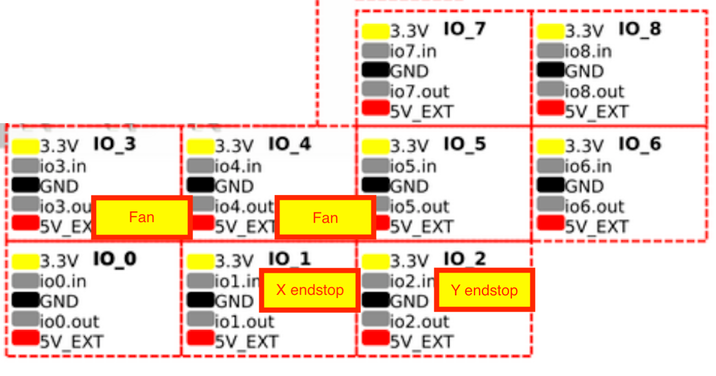
The fans and the end stops are both two wire plugs. Does it matter (as long as the two pins are right) which wire goes to which pin?
The two fans, I’m assuming are the hot end and part cooling fans. I have a fan (also 2 wire) that I’d like to use to cool the mainboard and I’m not sure where that would go.
Thanks much!
; Configuration file for Duet 3 (firmware version 3)
; executed by the firmware on start-up
;
; generated by RepRapFirmware Configuration Tool v2.1.8 on Tue Mar 17 2020 20:22:10 GMT-0500 (Central Daylight Time); General preferences
G90 ; send absolute coordinates...
M83 ; ...but relative extruder moves
M550 P"Duet 3" ; set printer name; Drives
M569 P0.0 S1 ; physical drive 0.0 goes forwards
M569 P0.1 S1 ; physical drive 0.1 goes forwards
M569 P0.2 S1 ; physical drive 0.2 goes forwards
M569 P0.3 S1 ; physical drive 0.3 goes forwards
M584 X0 Y1 Z2:3 E4 ; set drive mapping
M350 X16 Y16 Z16 E16 I1 ; configure microstepping with interpolation
M92 X80.00 Y80.00 Z4000.00 E420.00 ; set steps per mm
M566 X900.00 Y900.00 Z12.00 E120.00 ; set maximum instantaneous speed changes (mm/min)
M203 X6000.00 Y6000.00 Z180.00 E1200.00 ; set maximum speeds (mm/min)
M201 X500.00 Y500.00 Z20.00 E250.00 ; set accelerations (mm/s^2)
M906 X800 Y800 Z800 E800 I30 ; set motor currents (mA) and motor idle factor in per cent
M84 S30 ; Set idle timeout; Axis Limits
M208 X0 Y0 Z0 S1 ; set axis minima
M208 X300 Y300 Z400 S0 ; set axis maxima; Endstops
M574 X1 S0 P"io1.in" ; configure active-low endstop for low end on X via pin io1.in
M574 Y1 S0 P"io2.in" ; configure active-low endstop for low end on Y via pin io2.in
M574 Z1 S2; Z-Probe
M950 S0 C"io7.out" ; create servo pin 0 for BLTouch
M558 P9 C"io7.in" H5 F120 T6000 ; set Z probe type to bltouch and the dive height + speeds
G31 P500 X0 Y0 Z2.5 ; set Z probe trigger value, offset and trigger height
M557 X15:215 Y15:195 S20 ; define mesh grid; Heaters
M308 S0 P"temp0" Y"thermistor" T100000 B4138 ; configure sensor 0 as thermistor on pin temp0
M950 H0 C"out0" T0 ; create bed heater output on out0 and map it to sensor 0
M143 H0 S120 ; set temperature limit for heater 0 to 120C
M307 H0 B1 S1.00 ; enable bang-bang mode for the bed heater and set PWM limit
M140 H0 ; map heated bed to heater 0
M308 S1 P"temp1" Y"thermistor" T100000 B4138 ; configure sensor 1 as thermistor on pin temp1
M950 H1 C"out1" T1 ; create nozzle heater output on out1 and map it to sensor 1
M143 H1 S280 ; set temperature limit for heater 1 to 280C
M307 H1 B0 S1.00 ; disable bang-bang mode for heater and set PWM limit; Fans
M950 F0 C"out3" Q500 ; create fan 0 on pin out3 and set its frequency
M106 P0 S0 H-1 ; set fan 0 value. Thermostatic control is turned off
M950 F1 C"out4" Q500 ; create fan 1 on pin out4 and set its frequency
M106 P1 S1 H1 T45 ; set fan 1 value. Thermostatic control is turned on; Tools
M563 P0 D0 H1 F0 ; define tool 0
G10 P0 X0 Y0 Z0 ; set tool 0 axis offsets
G10 P0 R0 S0 ; set initial tool 0 active and standby temperatures to 0C; Custom settings are not defined
-
The bottom figure you posted suggests that you're trying to plug fans into io ports - this won't end well. If they're standard cooling fans with just two pins then start by moving them to out7 and out8 then change your config to reflect this... it seems that your current config think the fans are on out3 and out4...?!
-
Include
M122with wiring as isWeird the number of drivers for the different error change over timer; but just rule out something being wrong with the board - does it happen with no motors attached, and does the driver chips actually get warm?
Also see if
M122changes with motors disconnected.At a glance i couldn't see anything immediately wrong but will take a closer look in the morning if its not sorted by then. GL!The guy over should be correct, good call! -
I'll give that a try! Not sure of the new correct notation reflecting out7 and out8.
Thanks!
-
I guess I just change out3 to out7 and out4 to out8?
-
@BearcatTD
Yup
I see one is set as thermostatic and the other not, so if you heat the nozzle and the wrong fan starts (ie the part cooling fan rather than the heatsink fan), then swap the connections (or out7 with out8 in the config).
-
@bearer said in CR10v2 - Duet 3 Connections - Part 2:
Include M122with wiring as is
Not 100% sure what you mean by this.
Weird the number of drivers for the different error change over timer; but just rule out something being wrong with the board - does it happen with no motors attached, and does the driver chips actually get warm?
I'll unplug the the drivers and see. I'll also check and see if the drivers were warm. I felt them earlier and they didn't seem warm.
Also see if M122 changes with motors disconnected. At a glance i couldn't see anything immediately wrong but will take a closer look in the morning if its not sorted by then. GL!
Not sure about this either!
Thanks for your help!
Pat
-
So I'm working on the fan(s)...
This is my current fan section of my config.g:
; Fans
M950 F0 C"out7" Q500 ; create fan 0 on pin out7 and set its frequency
M106 P0 S0 H-1 ; set fan 0 value. Thermostatic control is turned off
M950 F1 C"out8" Q500 ; create fan 1 on pin out8 and set its frequency
M106 P1 S1 H1 T45 ; set fan 1 value. Thermostatic control is turned onI have my part cooling fan plugged into out7 and it works. The code above says it is thermostatically controlled. Do I want that?
The Hotend cooling fan is plugged into out8 but it is not working. I think I want that always on or also thermostatically controlled so that when it gets to, maybe, 50 degrees, it will pop on.
I have a motherboard cooling fan that I want on all the time. I'm assuming it would go into out9. How would I code this to be on all of the time?!
Thanks, Pat
-
Have you paired the wires from each stepper motor into phases using a multimeter (there are other ways of doing it too) and checked that you have connected one phase to the 2 pins at one end of the motor connector, and one phase to the 2 pins at the other end?
The driver messages you are getting suggest that either you have got all the stepper motor connections not phased correctly, or your board ha as fault with SPI communication to the driver chips that only occurs after a few minutes. Do not change the stepper motor wiring order without checking the phases.
I have my part cooling fan plugged into out7 and it works. The code above says it is thermostatically controlled. Do I want that?
No, the part cooling fan should not be thermostatically controlled.
-
@BearcatTD for determining wire pairs, see https://duet3d.dozuki.com/Wiki/Choosing_and_connecting_stepper_motors#Section_Identifying_the_stepper_motor_phases
When commissioning, the sensible thing to do is connect one thing (eg one motor, one temp sensor, one fan) at a time, and test it. Connecting everything, flipping the on switch, then trying to troubleshoot, is asking for trouble.
Ian
-
@dc42 said in CR10v2 - Duet 3 Connections - Part 2:
No, the part cooling fan should not be thermostatically controlled.
Thanks! How do I do the coding in config.g for my three fans?
Part Cooling Fan out7
Hot end cooling fan out8
Motherboard cooling fan, I would assume out9Thanks again,
Pat -
@droftarts said in CR10v2 - Duet 3 Connections - Part 2:
When commissioning, the sensible thing to do is connect one thing (eg one motor, one temp sensor, one fan) at a time, and test it. Connecting everything, flipping the on switch, then trying to troubleshoot, is asking for trouble.
You got that right!! I'll take a run at the motor phase link
Thanks!
-
@BearcatTD said in CR10v2 - Duet 3 Connections - Part 2:
How do I do the coding in config.g for my three fans?
Part Cooling Fan out7
Hot end cooling fan out8
Motherboard cooling fan, I would assume out9You can always use the RRF config utility again, either in part (just fill in the bits you need), or in it's entirety (by loading the json file it produced the last time you used it; click 'Use existing configuration' on the start page, and it will prompt you to upload the json file). Using the first method, I get:
 ; Fans
M950 F0 C"out7" Q500                         ; create fan 0 on pin out7 and set its frequency
M106 P0 C"Part cooling fan" S0 H-1           ; set fan 0 name and value. Thermostatic control is turned off
M950 F1 C"out8" Q500                         ; create fan 1 on pin out8 and set its frequency
M106 P1 C"Hot end fan" S1 H1 T45             ; set fan 1 name and value. Thermostatic control is turned on
M950 F2 C"out9" Q500                         ; create fan 2 on pin out9 and set its frequency
M106 P2 C"CPU fan" S1 H-1                    ; set fan 2 name and value. Thermostatic control is turned off

; Tools
M563 P0 D0 H1 F1                             ; define tool 0
The part cooling fan and CPU fan are not thermostatically controlled. You can set the CPU fan to thermostatic control, and then tie that to the temperature monitoring of the CPU (setting this up is not supported in config tool) with:
M308 S2 Y"mcu-temp" A"MCU"         ; create sensor for mcu, shows on temp graph
M950 F2 C"out9" Q500               ; create fan 2 on pin out9
M106 P2 C"CPU fan" S1 H2 T45       ; set fan 2 name and value, use sensor 2
Not tested, but I think that should work.
Ian
-
@droftarts said in CR10v2 - Duet 3 Connections - Part 2:
You can always use the RRF config utility again,
do you know if anyone looked at how he ended up with mixed pin names for duet3 and duex5 initially? (from the configurator)
-
Thanks guys...Fans. Are. Working.
OK. Motor phases. I went through for each driver and phound the two wires that were in phase. Now I'm not quite sure what to do with them!
Thanks again!
-
@BearcatTD said in CR10v2 - Duet 3 Connections - Part 2:
Now I'm not quite sure what to do with them!
connect them ^^
one coil on the 1st and 2nd pin, the other coil on the 3rd and 4th pin. You can start on the left or the right, doesn't matter, if the motor turns the "wrong" way you can swap the coils or invert in config.
-
Thanks! Just so I'm hearing this right...
I would attach one of the "phase" wires to pin 1 or 2 and the other "phase" wire to pin 3 or 4. Does it matter which pins the other two wires go to ?
I apologize...this is probably maddening to you!
-
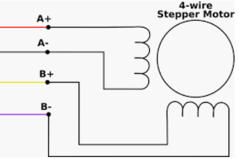
maybe that helps; keep the two wires that makes up a coil next to each other and it'll turn. if you got it "wrong" it'll just turn the "wrong" way, but lacking any standardized colour code or datasheet just wing it and change the direction in config after.
-
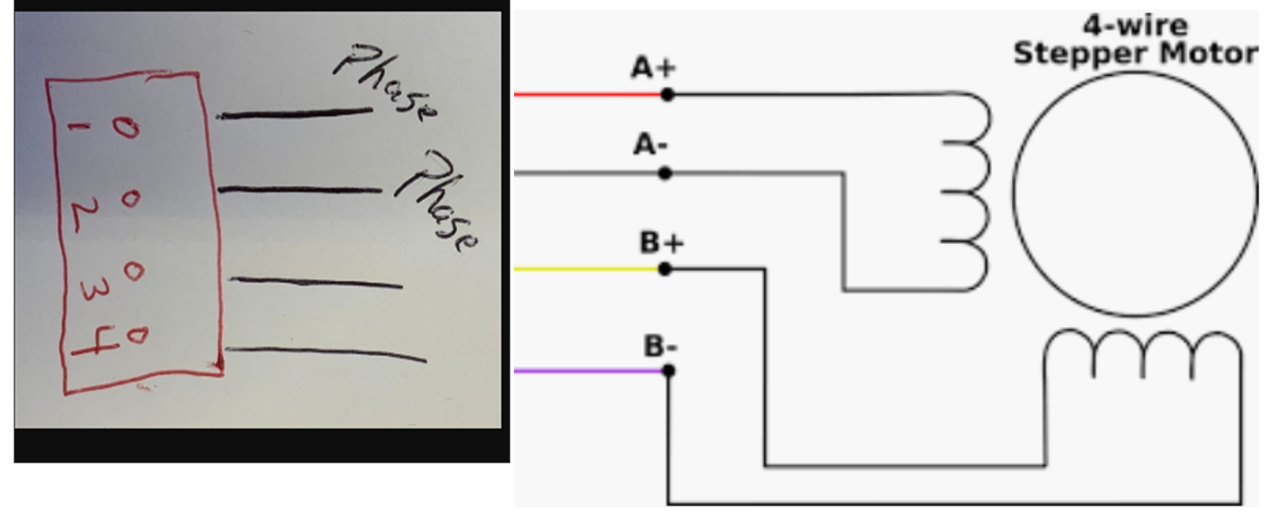
Bearer...I'm pretty thick. OK Here is a pretty picture I drew (my macbook croaked dead away this morning)
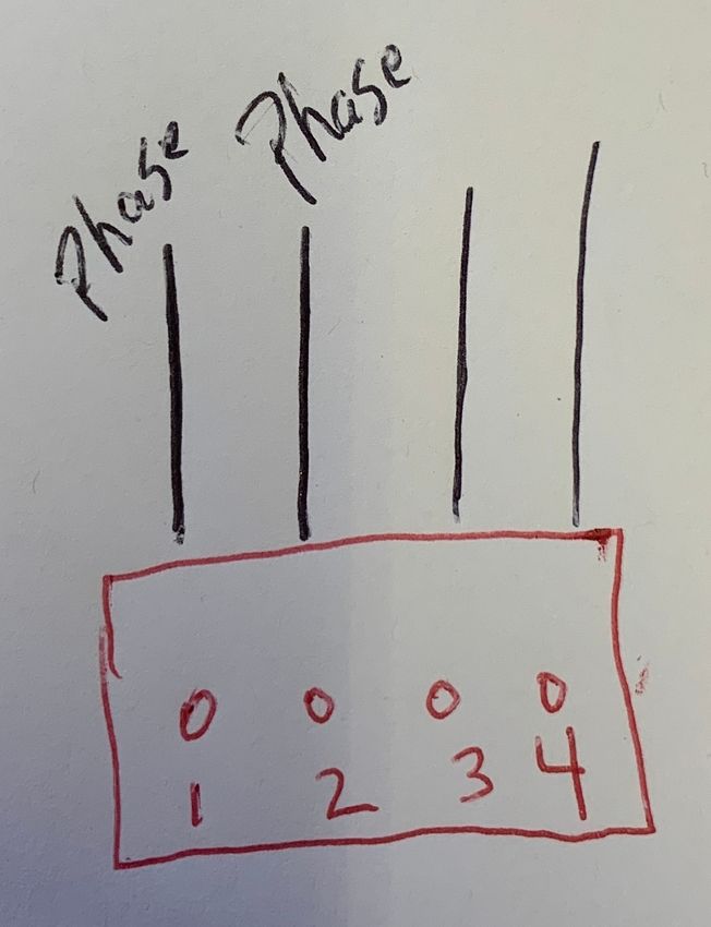
I'm not quite sure what constitutes a coil. So in the above image, this is what I originally had. So for attempt 1 I left pin one the same and I swapped pins 2 & 3. I got an error, "motor phase A may be disconected reported by driver(s) 2 3" Then the same error for phase B. For what is's worth, I also got "Failed to enable endstops", but we'll deal with that later.
Second attempt I swapped pins 1 & 3 and got the same errors.
I hope this makes sense... Thanks again for your time. I know you're in England, but I seriously owe you multiple beers!
-
@BearcatTD said in CR10v2 - Duet 3 Connections - Part 2:
in England
Lord no! (no offence to our British friends..)
While I'm not sure what you refer to as a phase, lets try to assume we mean the same thing. if you measure a resistance between 1 and 2 on your drawing, it should be correct; the two other wires go on 3 and 4. You should not measure any resistance between 1&3, 1&4 and 2&4, just to eliminate any shorts in the motor.
If thats the case then we can put the two pictures together to try and see how it fits together.
