Duex5 PWM Issues
-
Hi All,
I'm trying to set up a BLTouch on my Duet2 Wifi with Duex5 expansion. I've followed all the usual tutorials a few times over - even went so far as disabling ALL heaters, and trying multiple BLTouch sensors across multiple PWM channels, and I'm getting NO response from the BLTouch at all. Not even the power on self-test or a red light.
I've tested the sensors with a known 5v power source, and they work just fine. I've tested the PWM channels on the Duex5 with a multimeter, and I'm only getting a few mV across the GND and 5V pins...Questions:
- Are the PWM channels supposed to have 5V at all times (power on)?
- Do I need to enable the PWM channels? If so, how?
Full disclosure:
My boards are clones. Supply issues made getting genuine ones impossible. I'm trying to understand the functionality as designed before I troubleshoot the clone issue.Thanks in advance.
-
-
Config.g attached.
Board: Duet WiFi 1.02 or later + DueX5
Firmware: RepRapFirmware for Duet 2 WiFi/Ethernet 2.05 (2019-12-13b1)
Duet WiFi Server Version: 1.21[0_1585625158197_config.g](Uploading 0%)Machine is a custom built COREXY
Is there any other relevant information I've missed?
-
@Gerrard said in Duex5 PWM Issues:
Not even the power on self-test or a red light.
Post a picture of how you have it wired.
Your config.g upload didn't work. Copy and paste the text please.
-
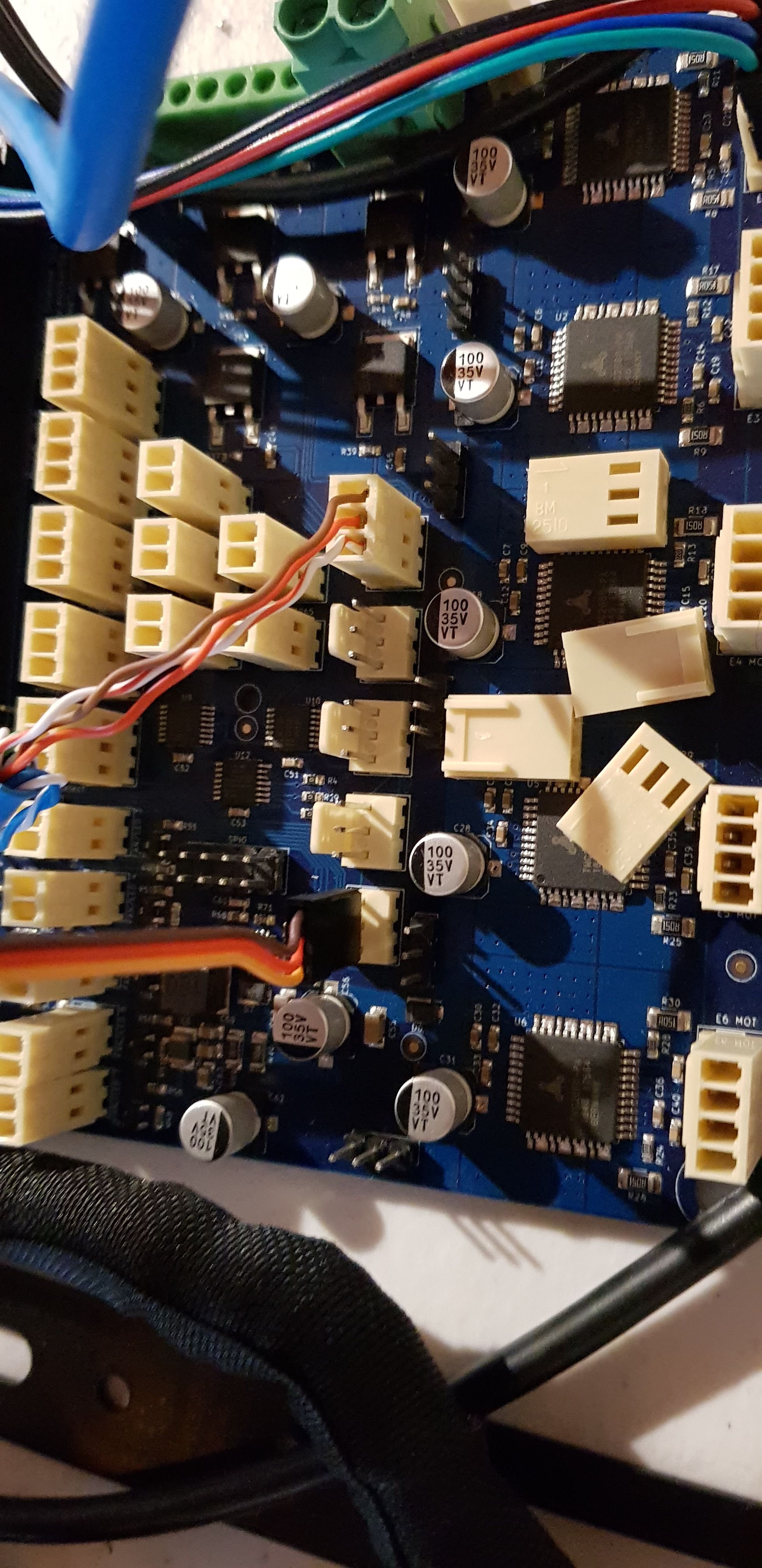
See attached image, and config.g content below.
You'll notice that I've disabled heaters 3 thru 7 in config.g. This is just a brute force approach to the confusing designation of heaters and PWM channels. I also tried a more direct approach, and that didn't work either.
Not to sound ungrateful, but I'm more keen on just getting my 2 x questions answered rather than diagnosing other potential issues. I'll move on to further diagnosis once I've eliminated these two questions.
Thanks.

; Configuration file for Duet WiFi (firmware version 2.03) ; executed by the firmware on start-up ; ; generated by RepRapFirmware Configuration Tool v2.1.8 on Mon Mar 30 2020 11:14:18 GMT+1000 (Australian Eastern Standard Time) ; General preferences G90 ; send absolute coordinates... M83 ; ...but relative extruder moves M550 P"FLSun G CoreXY" ; set printer name M667 S1 ; select CoreXY mode ; Network M552 S1 ; enable network M586 P0 S1 ; enable HTTP M586 P1 S0 ; disable FTP M586 P2 S0 ; disable Telnet ; Drives M569 P0 S0 ; physical drive 0 goes backwards M569 P1 S1 ; physical drive 1 goes forwards M569 P2 S0 ; physical drive 2 goes backwards M569 P5 S0 M569 P3 S0 ; physical drive 3 goes backwards M584 X0 Y1 Z2:5 E3 ; set drive mapping M350 X16 Y16 Z16 E16 I1 ; configure microstepping with interpolation M92 X80.00 Y80.00 Z1600.00 E420.00 ; set steps per mm M566 X480.00 Y480.00 Z12.00 E120.00 ; set maximum instantaneous speed changes (mm/min) M203 X60000.00 Y60000.00 Z300.00 E1200.00 ; set maximum speeds (mm/min) M201 X400.00 Y400.00 Z10.00 E250.00 ; set accelerations (mm/s^2) M906 X800 Y800 Z1600 E800 I30 ; set motor currents (mA) and motor idle factor in per cent M84 S30 ; Set idle timeout ; Axis Limits M208 X0 Y0 Z0 S1 ; set axis minima M208 X800 Y860 Z750 S0 ; set axis maxima ; Endstops M574 X1 Y1 Z1 S1 ; set active high endstops ; Z-Probe M307 H3 A-1 C-1 D-1 ; disable heater on PWM channel for BLTouch M307 H4 A-1 C-1 D-1 ; disable heater on PWM channel for BLTouch M307 H5 A-1 C-1 D-1 ; disable heater on PWM channel for BLTouch M307 H6 A-1 C-1 D-1 ; disable heater on PWM channel for BLTouch M307 H7 A-1 C-1 D-1 ; disable heater on PWM channel for BLTouch M558 P9 H5 F120 T6000 ; set Z probe type to bltouch and the dive height + speeds G31 P500 X21.6 Y9.4 Z2.5 ; set Z probe trigger value, offset and trigger height M557 X20:780 Y20:780 S20 ; define mesh grid ; Heaters M307 H0 B0 S1.00 ; disable bang-bang mode for the bed heater and set PWM limit M305 P0 T100000 B4138 R4700 ; set thermistor + ADC parameters for heater 0 M143 H0 S120 ; set temperature limit for heater 0 to 120C M305 P1 T100000 B4138 R4700 ; set thermistor + ADC parameters for heater 1 M143 H1 S280 ; set temperature limit for heater 1 to 280C ; Fans M106 P0 S0 I0 F500 H1 T45 ; set fan 0 value, PWM signal inversion and frequency. Thermostatic control is turned on M106 P1 S1 I0 F500 H-1 ; set fan 1 value, PWM signal inversion and frequency. Thermostatic control is turned off ; Tools M563 P0 D0 H1 F0 ; define tool 0 G10 P0 X0 Y0 Z0 ; set tool 0 axis offsets G10 P0 R0 S0 ; set initial tool 0 active and standby temperatures to 0C ; Custom settings are not defined -
@Phaedrux said in Duex5 PWM Issues:
Post a picture of how you have it wired.
To clarify - both of the connectors in the image attached are for BLTouch sensors. I had a spare so I plugged use that one (bottom of the two connectors) as a test and checked it across ALL other PWM Channels. No success on any of them.
-
@Gerrard said in Duex5 PWM Issues:
.Questions:
Are the PWM channels supposed to have 5V at all times (power on)?
Depends.
On 2 pin Fan and Heater ports, PWM is accomplished by switching ground. Depending on exactly how PWM is configured, a given channel could be sitting in the "low" part of the square wave, meaning the ground is in a high impedance state, and a DVM will only read a few mV.
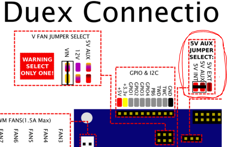
3 pin PWM ports should have +5 and Ground, and these two should always read 5V on a DVM. The switching is accomplished on the third pin. The most common reason to not have 5V (barring a failure) would be the jumper in the red circle below.
Note that Duex PWM 1 through 5 are just a different physical pinout for Duex Heater 2 through 6.
Do I need to enable the PWM channels? If so, how?
Sort of. In V2 firmware, you must "undefine" the heater (because Duex PWM and heaters are the same pins). Your photo looks like you are plugged into PWM 5 (which is heater 6), so:
M307 H6 A-1 C-1 D-1 ; undefine Heater 6 to allow PWM 5 to be used for BLt
Note that you also need to define the probe itself, something like this. Nothing to do with pins, just mentioning that it must exist for the probe to work.
M558 P9 H5 F100 T2000
The real tie between the H6 in the M307 command and the probe comes in the 'deployprobe.g' and 'retractprobe.g' macros. For example, the deploy will have:
M280 P6 S10 I1
The P6 is the tie, and I1 is important to invert the duty cycle of the square wave.
Summary to "enable it?"
Undefine a heater to free up a pin
Define a probe
The pin used is implicit in the deploy/retract macros M280 command P6 parm.
-
Good pick up! you were right, it was the jumper missing.
This is a new board (with no instructions), so all jumpers were missing. I've added that, and I now have the BLTouch doing a self test - Now for the bed levelling.Side note: I mis-read your diagram, and added a jumper to the 3 pins visible in your image, not the Aux Jumper select pins (just out of the image)... Then I realised there was probably others missing, so I came back and realised my error.
Thanks for your help!
-
Excellent!! Always glad to see progress.
-
@Gerrard said in Duex5 PWM Issues:
but I'm more keen on just getting my 2 x questions answered rather than diagnosing other potential issues.
No worries. The reason I ask before spending much time diving too deeply is that often times it's a simple miss, or a combination of errors. Having the full picture saves me time in the long run.
Glad you got it sorted out.